KE-750_MS.pdf - 第67页
3. Convey or Motor Replacement – IN / OUT Motor (1) Remove motor relay cable from connector. (2) Loosen stop screw of motor bracket A and remove drive belt from motor pulley A. (3) Remove motor. (4) If motor pulley A has…

Chapter 5 PWB Conveyor Unit
1. Conveyor Belt Replacement
(1) Loosen tension adjustment pulley.
(2) Remove conveyor belt from conveyor pulley and replace.
(3) Without putting tension on the conveyor belt use a magic marker to mark a 200mm interval. Stretch
the belt with the pulley loosened in (1) above until the interval increases to 202mm and tighten.
A
djustment pulle
y
2. Conveyor Pulley Replacement
There are 3 types of conveyor pulley assembly. If the assembly is changed, pulley may not rotate.
Assemble as shown below.
Spring washer WS0410002KN
Flat washer WP0403081SC
Screw
SM6042510SC
Nut NM6040001SC
Screw
SM4042501SC
Nut
NM6040001SC
Pulley B assy E20897210A0
Pulley spacer E2055721000
Pulley assy
E21117150A0
Flat washe
r
WP04030800SC
Nut
NM6040001SC
Screw
SM6040810SC
Pulley assy
E21117150A0
Flat washe
r
WP0430800SO
Spring washer WS0410002KN
Flat washer WP0403081SC
1-59
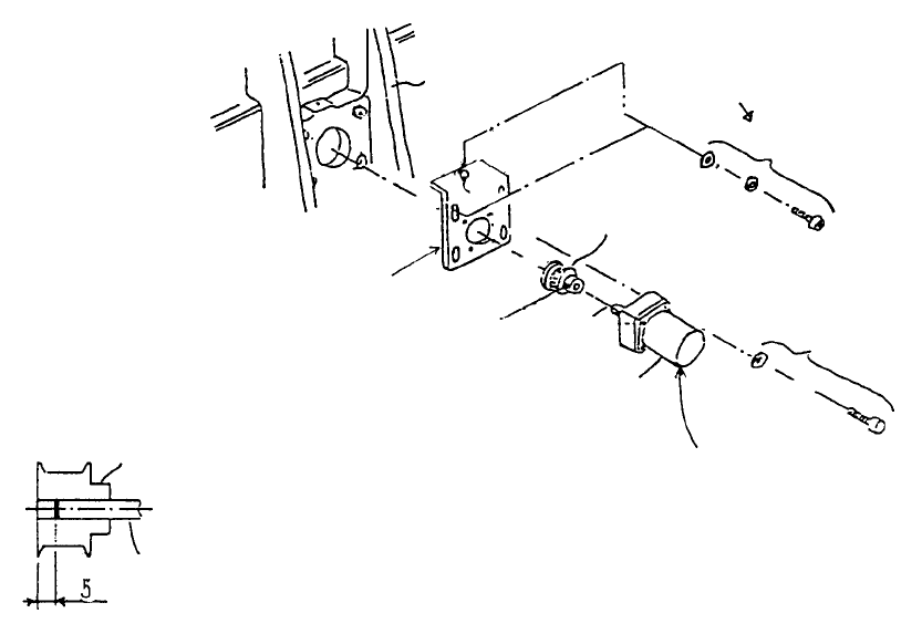
3. Conveyor Motor Replacement
– IN / OUT Motor
(1) Remove motor relay cable from connector.
(2) Loosen stop screw of motor bracket A and remove drive belt from motor pulley A.
(3) Remove motor.
(4) If motor pulley A has been replaced, position so that the end of motor shaft penetrates to 5mm
from the motor pulley face and tighten.
(5) Reassemble by following procedures (1)~(3) in reverse sequence. Drive belt tension is
determined by motor bracket height but it is not necessary to tighten the vertical screw all the way.
Set so that belt neither flops nor is overstretched.
Conveyor moto
r
shaft
Motor pulley A
* Fasten motor pulley A as shown belo
w
IN motor cable ass
y
E94807210A0
OUT motor cable assy
E94827210A0
A
lign so that cable is
oriented to side.
A
ccessory screw fo
r
conveyor motor
Stop scre
w
SM8030602TP
Motor bracket A
E2171721000
Motor bracket A
E2172721000
SEMS cap scre
w
SL6051092TN
Rail stand F
(Left side)
1-60
– CNT Motor
(1) Loosen stop screw in motor bracket and remove drive belt C from motor pulley A.
(2) Remove motor
(3) If replacing motor pulley A, align motor shaft face with pulley face when assembling.
(4) To reassemble, follow procedures (1), (2) in reverse sequence.
CNT motor shaft
Motor pulley A
SL6051292TN
Motor accessor
y
stop screw
CNT motor cable ass
y
E94787250A0
Motor bracket
E2021725000
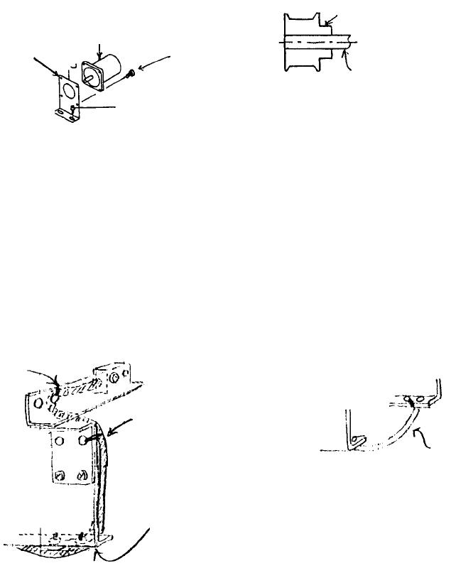
4. PWB Detecting Sensor Replacement
– IN/OUT Sensors
(1) Remove stop screw SI6031092TN from sensor body. Replace sensor cable assy.
(2) Refer to QA Table, Conveyor No. 6 for instructions on sensor positioning adjustment.
(3) Organizing cables
Tie cable to 2 holes each in
bottom of fixed & movable
rails.
A
rrange slack so cable stays
inside cover when rails are
close together.
(*) When back is standard
Tie to 2 holes in
bottom of rail plate
Tie to hole in senso
r
bracket A
Tie to hole in senso
r
bracket B
1-61