KE-750_MS.pdf - 第70页
5. BU Plate UP/DOWN Sensor Replacement (1) Disconnect sensor body and relay cable. (2) Replace sensor. (3) For adjustment of sensor positioning, refer to QA Table, Conveyor No. 11. BU table UP position BU tool BU table D…
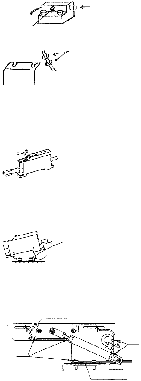
– WAIT Sensor
(1) Remove fiber from amp.
(2) Remove fiber from guide block.
Push here.
Loosen here.
(3) Remove fiber from sensor bracket. For instructions on setting sensor level, refer to QA Table.
– Assembling fiber amp unit
(1) Gently lift top of amp unit with a finger nail or screwdriver.
(2) Push fiber all the way to the back of the amp unit and trip lever.
(3) For thin fibers, first insert the thin attachment all the way into the amp, then insert and fasten
fiber.
– Mounting amp unit
Use the special mounting bracket supplied.
(1) Fit groove in front part (A) of amp unit onto special mounting bracket.
(2) Fit rear part (B) of amp unit completely onto special mounting bracket.
(3) To remove, insert screwdriver into groove (C). While pulling back, raise unit.
Special bracket
– STOP/C. OUT Sensors
(1) Remove stop screw SL4031291SC from sensor body and replace sensor cable assy.
(2) For instructions on adjusting sensor positioning, refer to QA Table, Conveyor No. 1.
(3) Organizing cables
Cable tie
Pass through gap o
f
cylinde
r
& stopper frame.
Cable ties
Connect to stopper frame.
1-62
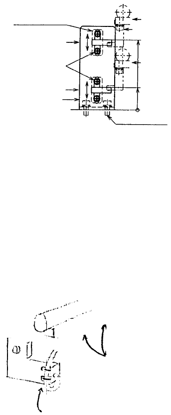
5. BU Plate UP/DOWN Sensor Replacement
(1) Disconnect sensor body and relay cable.
(2) Replace sensor.
(3) For adjustment of sensor positioning, refer to QA Table, Conveyor No. 11.
BU table UP position
BU tool
BU table DOWN
position
Provisional fastening
position
Provisional fastening
position
2092 SEMS cap screw
BU sensor sta
y
BU table sensor (DOWN)
HDOO stop screw
BU table sensor (UP)
BU sensor plate
6. T. PIN Sensor Replacement
(1) Remove adjustment screw and remove sensor from each sensor bracket.
(2) Replace sensor.
(3) For adjustment of sensor positioning, refer to QA Table, Conveyor No. 2.
(4) Organizing cables
Wrapped around front of senso
r
bracket & held with cable ties.
BU table rear fastening
base
1-63
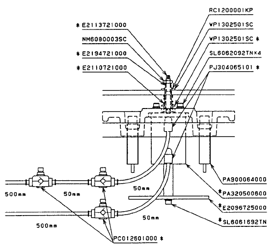
7. BU Cylinder Replacement
(1) Remove fastening nut.
(2) Place plate between base frame and BU plate stop screw at the bottom of the cylinder so that when
BU table is pushed down, E2113721000 does not sink.
(3) Push BU table down and remove RC1200001KP.
(4) Remove the 4 rubber plugs in BU table and remove the stop screws from those holes.
(5) Remove cylinder by pulling it towards yourself from bottom of conveyor unit.
(6) Replace cylinder and reassemble in reverse sequence.
(7) For instructions on adjusting BU table height, refer to QA Table, Conveyor No. 4.
c When the parts marked with * are attached and placed at the bottom of the conveyor unit,
insert screw SL6062092TN into the BU table fastening hole and tighten.
d Place plate between base frame and bottom of SL6061692TN so that E2113721000 does
not sink when BU table is pressed down.
e Push down on BU table to fit RC1200001KP in the peripheral groove of E2194721000.
f Rotate E2194721000 to adjust height and tighten NM6080003SC.
g Fit the 4 TA0750501R0 in the holes in the BU table.
h Assembly sequence
i Tube
1-64