KE-750_MS.pdf - 第88页
(9) While pressing surface A to surface B, fasten bracket with M4 SEMS caps . (10) Refer to Dia. 10 - 1 - 2 and connect camera cable assy to camera. (11) Remount light base by following step (1) in reverse sequence. E345…
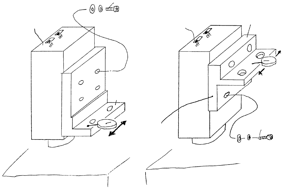
(7) As shown below, pass a dial gauge over the surface and adjust. When dial reads to within 0.5mm,
tighten screw. (Camera and bracket may be set to any convenient height.)
(8) Attach TLC lens (E3723700000) to CCD camera. Leave the 4 focus adjust stop screws loose.
BedBed
Coat with
Locktite 242
A
llen head screw SM6020752TP
Spring washer WS0210002KN
Flat washer WP0220301SC
Careful with protrusion
(Thinner on lens side)
VCS camera
bracket B
CCD camera
A
llen head screw M2 x 7
SM6020752TP
Spring washer WS0210002KN
Flat washer WP0220301SC
VCS camera bracket A
Coat with Locktite 242
CCD camera
VCS 0.3 Assy (OPT)VCS 0.4 Assy (STD)
Fig. 8-1-3
1-80
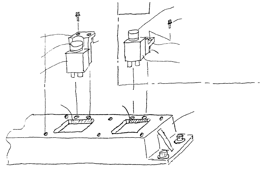
(9) While pressing surface A to surface B, fasten bracket with M4 SEMS caps.
(10) Refer to Dia. 10 - 1 - 2 and connect camera cable assy to camera.
(11) Remount light base by following step (1) in reverse sequence.
E345272500
Base bridge (760)
E9617721000
CCD camera
E3715725000
VCS camera bracket B
SEMS cap screw (with
spring & flat washers)
(M4 x 14)
E3723700000
TLC lens
Optional
SEMS cap screw
(with spring & flat
washers)
(M4 x 14)
E3723700000
TLC lens
E9617721000
CCD camera
E3701725000
VCS camera bracket A
Fig. 8-1-4
1-81
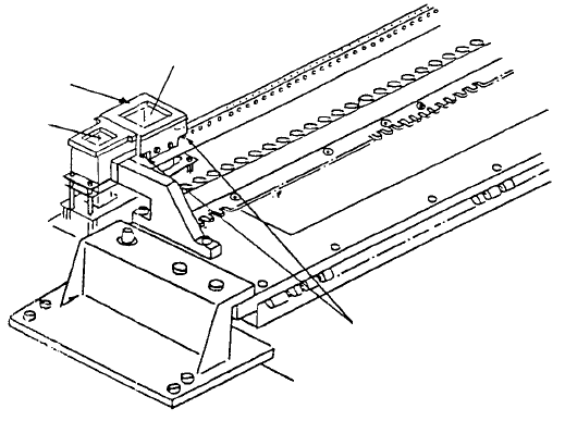
2. Adjustment after CCD Camera / Lens Replacement
(1) Camera focus adjustment
1) Attach VCS HT jig.
2) Once camera is receiving live images from the monitor, for VCS(0.4) assy & VCS(0.3) assy
respectively, position VCS jig plates A & C over VCS HT jig so focus target image is picked up by
the monitor.
3) While watching monitor, rotate upper part of lens until grid pattern of focus target is distinct (rough
focus).
4) Overlay grid pattern in image monitor and adjust jig attitude so that the vertical and horizontal
form a grid pattern. After completing adjustment, cancel grid pattern in the monitor.
Note: Tighten scre
w
of VCS HT jig
while pressing parallel pin.
Parallel pin
VCS(0.3)
VCS HT jig
VCS(0.4)
Fig. 8-2-1
1-82