KE-750_MS.pdf - 第90页
5) Connect IMG-P PWB assy to an oscilloscope. To focus the camera on the VCS(0.4) assy, connect CN2 1 pin to GDN as shown at right. To focus the camera on the VCS(0.3) assy, connect CN3 1 pin to GDN. 6) While watching th…
2. Adjustment after CCD Camera / Lens Replacement
(1) Camera focus adjustment
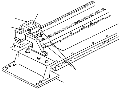
1) Attach VCS HT jig.
2) Once camera is receiving live images from the monitor, for VCS(0.4) assy & VCS(0.3) assy
respectively, position VCS jig plates A & C over VCS HT jig so focus target image is picked up by
the monitor.
3) While watching monitor, rotate upper part of lens until grid pattern of focus target is distinct (rough
focus).
4) Overlay grid pattern in image monitor and adjust jig attitude so that the vertical and horizontal
form a grid pattern. After completing adjustment, cancel grid pattern in the monitor.
Note: Tighten scre
w
of VCS HT jig
while pressing parallel pin.
Parallel pin
VCS(0.3)
VCS HT jig
VCS(0.4)
Fig. 8-2-1
1-82
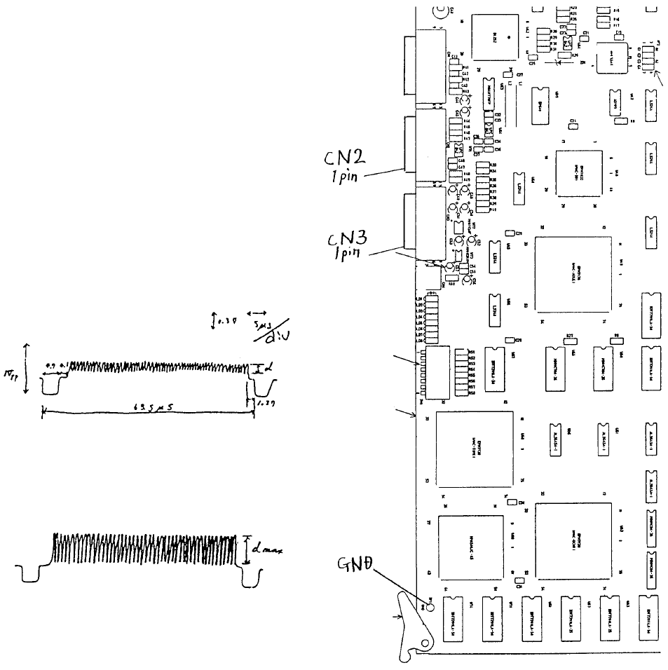
5) Connect IMG-P PWB assy to an
oscilloscope. To focus the camera on
the VCS(0.4) assy, connect CN2 1 pin
to GDN as shown at right.
To focus the camera on the VCS(0.3)
assy, connect CN3 1 pin to GDN.
6) While watching the oscilloscope, turn
the upper part of the lens until the
maximum band width appears. After
lens adjustment, tighten any one of the
4 screws in the lens.
(B) After adjustmen
t
(A) Before adjustmen
t
A
djust focus when d value is at
max.
Note: In reality, blank spaces blu
r
the wave form.
Fig. 8-2-3 Fig. 8-2-2
1-83
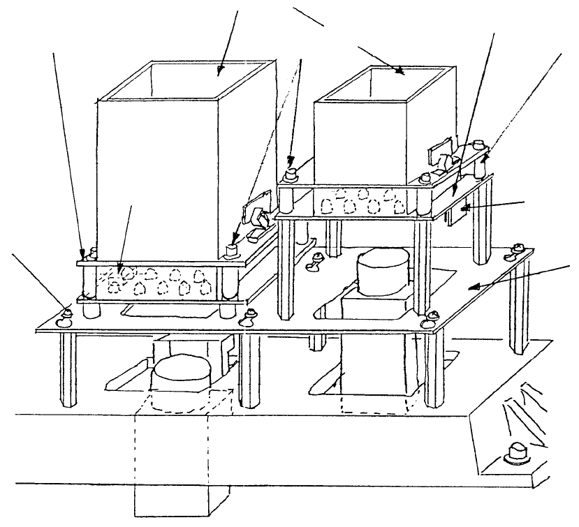
3. 0.4/0.3 VCS Light PWB Assy Replacement
(1) Disconnect cable from PWB connector
(2) Loosen the 4 Allen head screws. Push so that spacers do not fall and remove diffuser.
(Refer to Dia. 10 - 1 - (1) if there are difficulties. Remove light base and continue.)
M3 SEMS
screw
Light base
Connecto
r
Space
r
0.3 VCS light PWB ass
y
A
llen head scre
w
Diffuse
r
0.4 VCS light PWB ass
y
Fig. 8-3-1
1-84