5M-1751-004w_G5S.pdf - 第187页
5OM-1751 1304-001 5-A Chapter 5 Cable Connection Diagram This chapter describes the cable connection diagram. As this contains highly sophisticated contents, it should carefully be referred to.
4-61
5OM-1751
1304-001-(31012WN---1006)
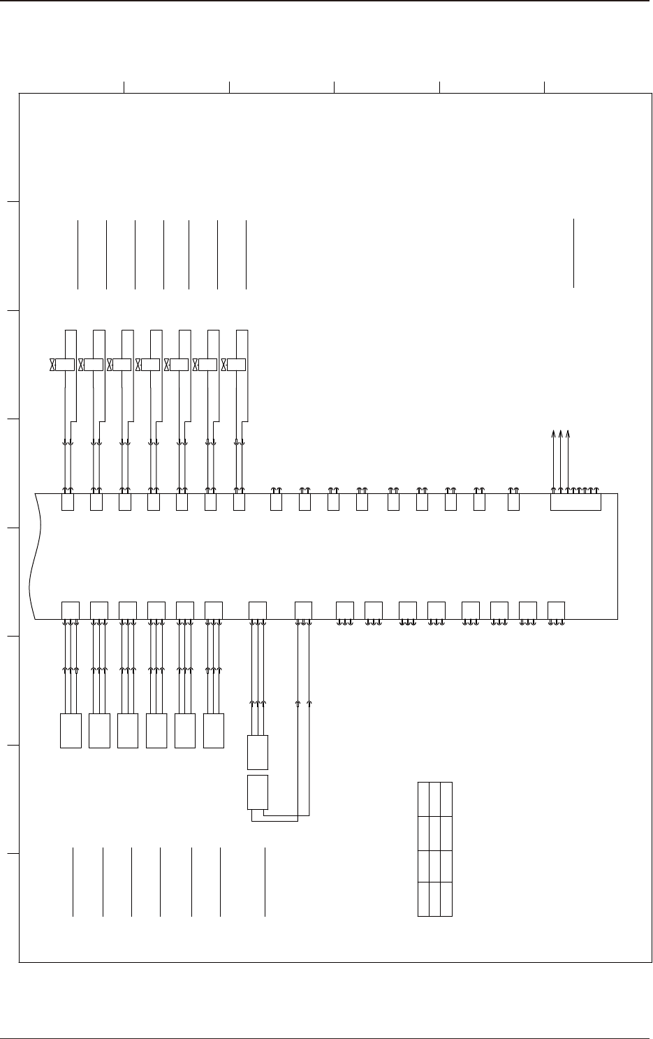
Transfer Section U08 I/O Circuit 2
1 2 3 4 5 6 7 8
A
B
C
D
E
F
X0836
X0831
X0830
X0812
X0813
X0815
X0814
B0830
B0830
:3
+
OUT
-
:2
:1
B0836
+
OUT
-
B0836T
-
+
B0836
:3
:2
:1
Movable Chute Back up Pin Sensor
X0832
X0833
B0831
:6
+
OUT
-
:5
:4
B0832
B0832
:3
+
OUT
-
:2
:1
B0833
+
OUT
-
Y0812
:5
:6
BK R
Z Clamp L Cylinder valve DOWN
Z Clamp L Cylinder valve UP
PCB Stopper 1 UP/DOWN valve
Y0813
:7
:8
BK R
Y0810
:1
:2
X0810
BK R
Y0811
:3
:4
BK R
Y0814
:9
:10
BK R
IN OUT
CN10
CN11
CN12
CN13
CN14
CN15
CN16
CN17
CN18
CN19
CN20
1
2
3
3
2
1
3
2
1
3
2
1
3
2
1
3
2
1
1
2
3
1
2
3
1
2
3
1
2
3
3
2
1
2
1
CN40
CN39
CN38
CN37
CN36
CN35
CN34
CN33
CN32
CN31
CN30
1
2
1
2
1
2
1
2
1
2
1
2
1
2
1
2
1
2
1
2
IO PCB
U08
PCB Stopper 2 UP/DOWN valve
Y0815
:11
:12
BK R
Z Clamp R Cylinder valve DOWN
Z Clamp R Cylinder valve UP
PCB Stopper 1 Rower Limit Detection
PCB Stopper 1 Upper Limit Detection
PCB Stopper 2 Rower Limit Detection
PCB Stopper 2 Upper Limit Detection
X0810
X0811
X0816
X0834
X0835
B0834
B0834
:3
+
OUT
-
:2
:1
B0835
+
OUT
-
PCB Stopper 3 Rower Limit Detection
PCB Stopper 3 Upper Limit Detection
PCB Stopper 3 UP/DOWN valve
Y0816
:1
:2
X0816
BK R
CN21
CN22
CN23
CN25
1
2
3
3
2
1
3
2
1
3
2
1
3
2
1
CN45
CN43
CN42
CN41
CN24
1
2
1
2
1
2
1
2
1
2
CN44
:1
:2
B0836T
BL
BK
BR
BL
BK
BR
BL
BK
BR
BL
BK
BR
BL
BK
BR
BL
BK
BR
BL
BK
BR
BL
BR
STLT_CNVR
X0837
:6
:5
:4
:6
:5
:4
B0830
B0832
B0834
X0810
X0810
X0810
X0810
X0810
CN27
1
2
X0827
3
4
5
6
7
8
B11003 :4
B21003 :4
B31003 :4
PCB Stop Sensor Left Remote
The name of the PCB stopper
varies depending on the flow direction.
Refer to the following table.
Stopper
1
Stopper
2
Stopper
3
L to R
R to L
L
L
R Long Size
R Long Size
PCB Stop Sensor Right Remote
Long Size PCB Stop Sensor Remote (OP)
[N-/03/2C]
Flow Direction

5OM-1751
1304-001 5-A
Chapter 5
Cable Connection Diagram
This chapter describes the cable connection diagram.
As this contains highly sophisticated contents, it should carefully be
referred to.

5OM-1751
1304-001 5-B