5M-1751-004w_G5S.pdf - 第68页
1-16 Pneumatic and Mounting Diagrams 5OM-1751 1305-002 Nozzle Stocker (Pneumatic Diagram) 8 4 5 6 2 3 9 1 Stocker 1 U/D From Main Body Shutter 1 Open / Close No. Name Q’ty No. Name Q’ty No. Name Q’ty No. Name Q’ty 1 T ub…
1-15
Pneumatic and Mounting Diagrams
5OM-1751
1305-002
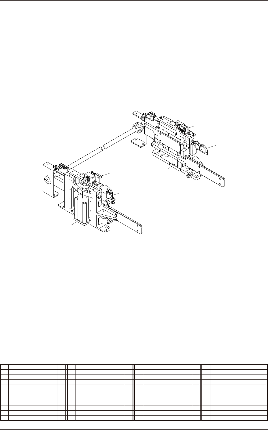
Positioning Unit (Mounting Diagram)
In Drop Prevention Unit Attachment
No. Name Q’ty No. Name Q’ty No. Name Q’ty No. Name Q’ty
7 Solenoid Valve 1
9 Cylinder 2
10 Solenoid Valve 1
11 Cylinder 2
9
7
9
9
10
11
11
1-16
Pneumatic and Mounting Diagrams
5OM-1751
1305-002
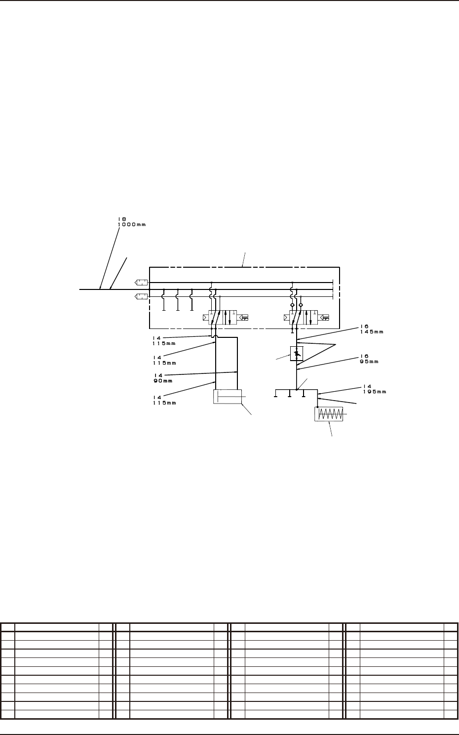
Nozzle Stocker (Pneumatic Diagram)
8
4
5
6
2
3
9
1
Stocker 1 U/D
From Main Body
Shutter 1 Open / Close
No. Name Q’ty No. Name Q’ty No. Name Q’ty No. Name Q’ty
1 Tube
φ
8 1
2 Tube
φ
6 1
3 Tube
φ
4 1
4 Solenoid Valve 1
5 Cylinder 1
6 Cylinder 1
8 Needle 1
9 Union Y 1
1-17
Pneumatic and Mounting Diagrams
5OM-1751
1305-002
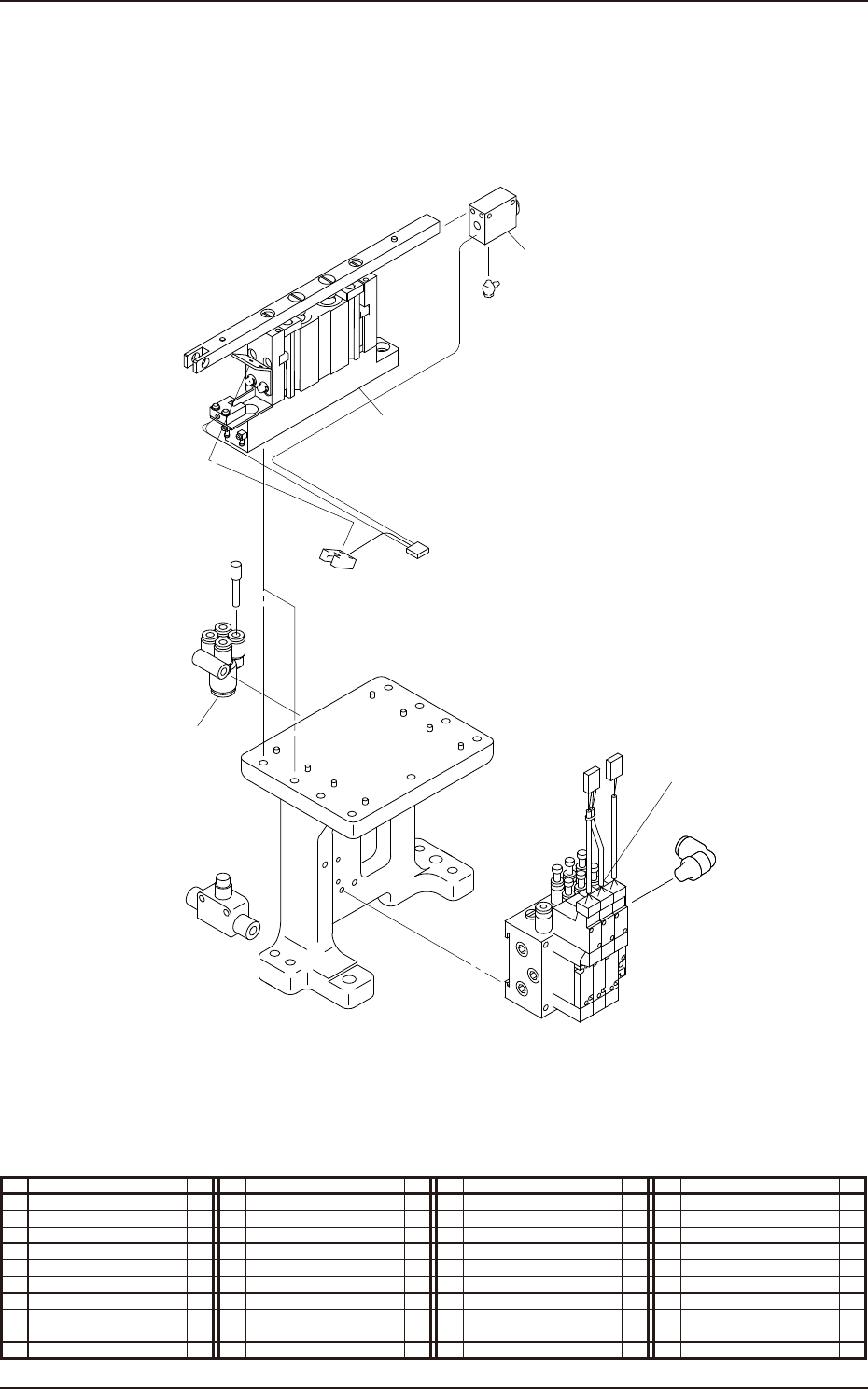
Nozzle Stocker (Mounting Diagram)
9
4
5
6
No. Name Q’ty No. Name Q’ty No. Name Q’ty No. Name Q’ty
4 Solenoid Valve 1
5 Cylinder 1
6 Cylinder 1
9 Union Y