5M-1751-004w_G5S.pdf - 第77页
1-25 Pneumatic and Mounting Diagrams 5OM-1751 2 1 3 4 Nozzle Stocker for Multi-Functional Nozzle (Mounting Diagram) 1305-002 No. Name Q’ty No. Name Q’ty No. Name Q’ty No. Name Q’ty 1 Solenoid V alve 3 2 Cylinder 1 3 Cyli…
1-24
Pneumatic and Mounting Diagrams
5OM-1751
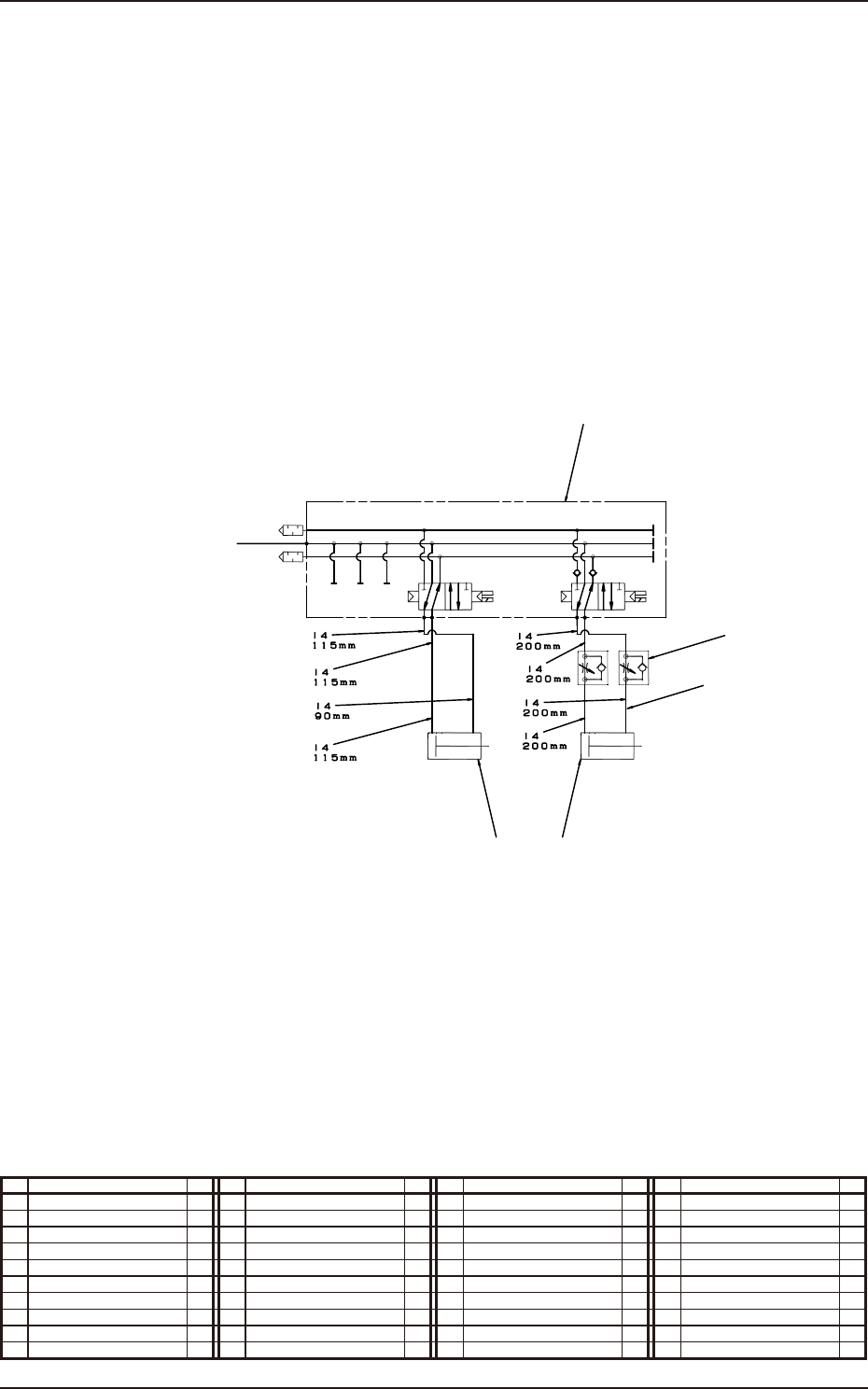
Nozzle Stocker for Multi-Functional Nozzle (Pneumatic Diagram)
No. Name Q’ty No. Name Q’ty No. Name Q’ty No. Name Q’ty
1 Tube
φ
4 1
2 Solenoid Valve 1
3 Speed Controller 2
4 Cylinder 1
5 Cylinder 1
1305-002
4
From the Inside of Whole Base
Stocker 1 U/D Shutter 1 Open/Close
5
2
3
1
1-25
Pneumatic and Mounting Diagrams
5OM-1751
2
1
3
4
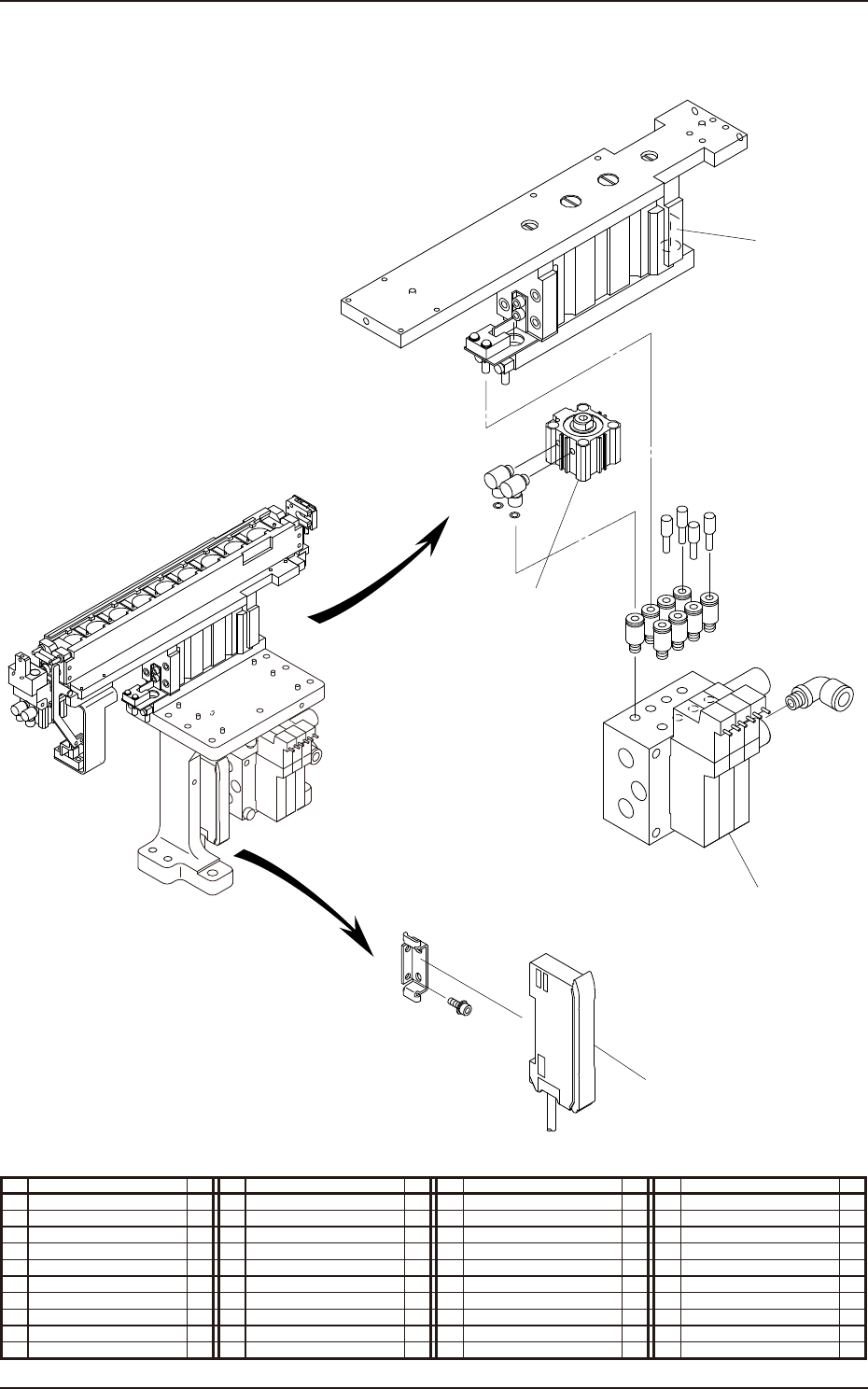
Nozzle Stocker for Multi-Functional Nozzle (Mounting Diagram)
1305-002
No. Name Q’ty No. Name Q’ty No. Name Q’ty No. Name Q’ty
1 Solenoid Valve 3
2 Cylinder 1
3 Cylinder 1
4 Sensor Amplier 1

5OM-1751
1304-001 2-A
Chapter 2
Sensor and Load Layout
This chapter indicates where the sensors and loads are located in each
section.
As this contains highly sophisticated contents, it should carefully be
referred to.