00198829-01_SM_X-Series-S_Hxxxx_EN.pdf - 第104页
5 Pneumatic System 5.12 Vacuum Pump 104 Service Manual SIPLACE X-Series S (from Hxxxx) 01/2021
5 Pneumatic System
5.12 Vacuum Pump
Service Manual SIPLACE X-Series S (from Hxxxx) 01/2021 103
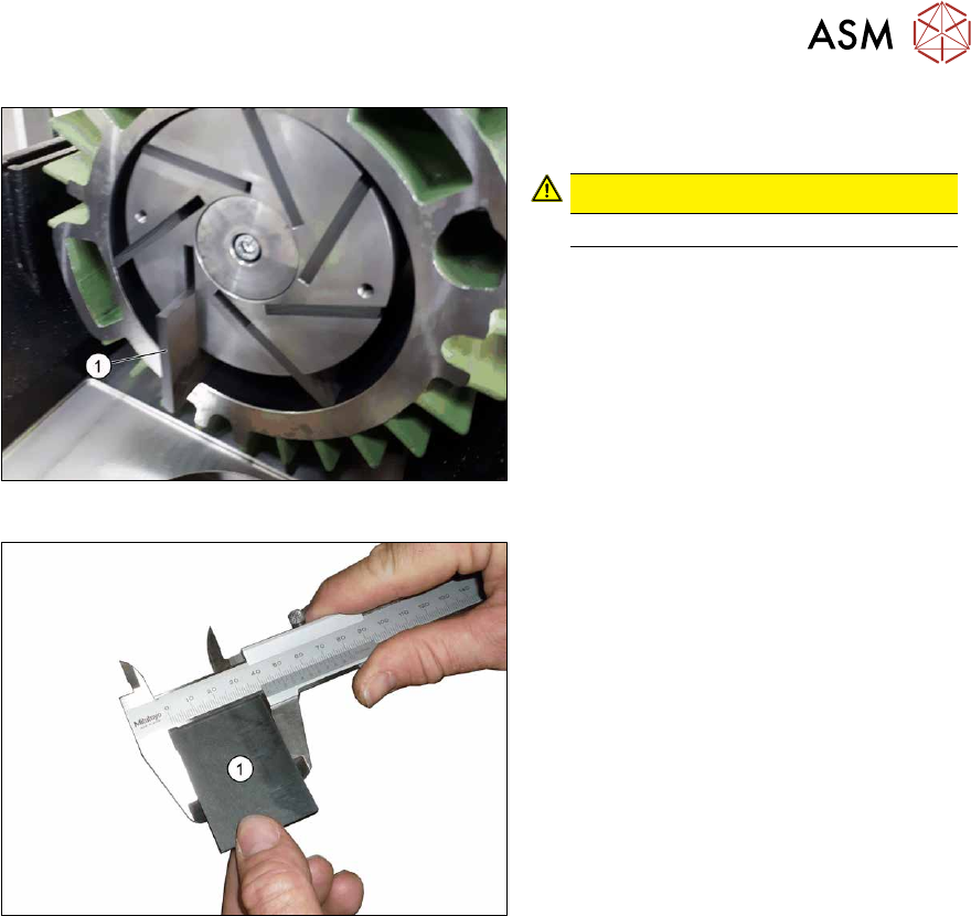
Fig.130: Sliders
► Carefully lever the slides (1) out of the
pump (7x).
CAUTION!
The slides are sensitive.
.
► Check the condition of the slides and
replace the slides, if required.
Fig.131: Measuring the width of the slides
► Measure the width of the slides. Re-
place the slide, if it does not reach the
required minimum width of 28 mm
.
Installation
► Follow the removal instructions in reverse order for installation.

5 Pneumatic System
5.12 Vacuum Pump
104 Service Manual SIPLACE X-Series S (from Hxxxx) 01/2021
6 Gantries
6.1 Overview of gantries
Service Manual SIPLACE X-Series S (from Hxxxx) 01/2021 105
6 Gantries
DANGER
Observe User Manual
► Please observe the safety instructions in the user manual for all work!
CAUTION
Use the correct blanking plugs
► Only use blanking plugs in the machine which match the manufacturer's compressed
air connection. A tight fit cannot be guaranteed for other blanking plugs.
► We recommend the use of blanking plugs made by Festo.
6.1 Overview of gantries
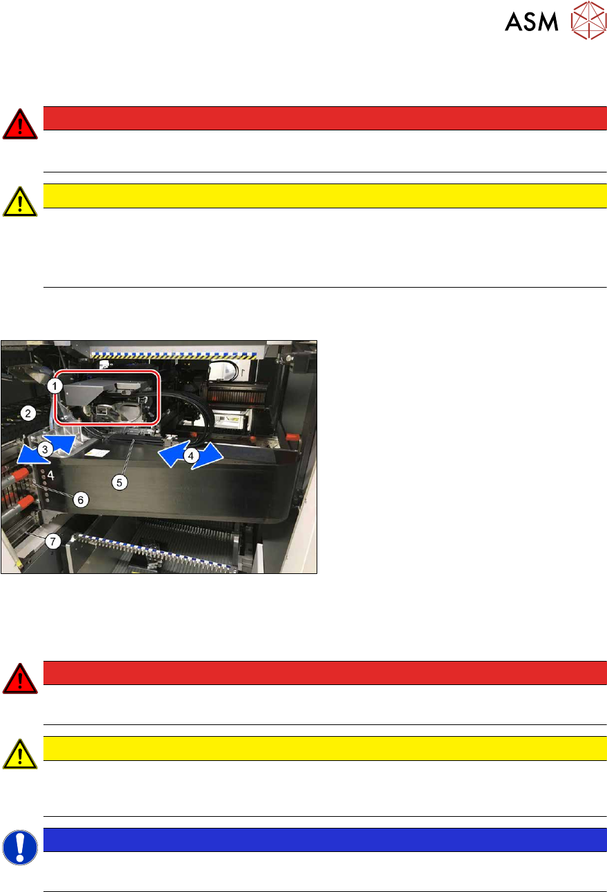
Fig.132: Overview of gantry
1. Head interface and Vision Head Inter-
face (under the cover)
The Vision Head Interface is fitted on
the head interface.
2. Y axis trailing cable
3. Y axis
4. X axis
5. X axis trailing cable
6. Y drive (primary)
7. Y scale
6.2 Replacing the Gantry
DANGER
Danger of crushing
The attraction force of the magnets is 400Nm.
CAUTION
Do not loosen or remove the screws
The loosening and removing of the fastening screws leads to tension. This has a negative
effect on the product life.
NOTICE
SIPLACE Service
This task may only be performed by SIPLACE service technicians.