00198829-01_SM_X-Series-S_Hxxxx_EN.pdf - 第106页
6 Gantries 6.3 X and Y axis 106 Service Manual SIPLACE X-Series S (from Hxxxx) 01/2021 6.3 X and Y axis 6.3.1 Replacing the X axis incremental encoder Parts, equipment and tools ● Select the correct incremental encoder: …
6 Gantries
6.1 Overview of gantries
Service Manual SIPLACE X-Series S (from Hxxxx) 01/2021 105
6 Gantries
DANGER
Observe User Manual
► Please observe the safety instructions in the user manual for all work!
CAUTION
Use the correct blanking plugs
► Only use blanking plugs in the machine which match the manufacturer's compressed
air connection. A tight fit cannot be guaranteed for other blanking plugs.
► We recommend the use of blanking plugs made by Festo.
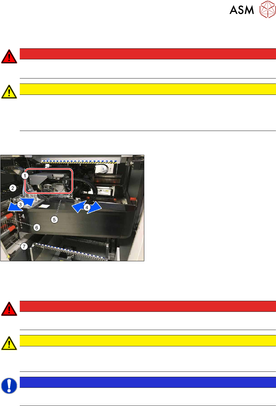
6.1 Overview of gantries
Fig.132: Overview of gantry
1. Head interface and Vision Head Inter-
face (under the cover)
The Vision Head Interface is fitted on
the head interface.
2. Y axis trailing cable
3. Y axis
4. X axis
5. X axis trailing cable
6. Y drive (primary)
7. Y scale
6.2 Replacing the Gantry
DANGER
Danger of crushing
The attraction force of the magnets is 400Nm.
CAUTION
Do not loosen or remove the screws
The loosening and removing of the fastening screws leads to tension. This has a negative
effect on the product life.
NOTICE
SIPLACE Service
This task may only be performed by SIPLACE service technicians.
6 Gantries
6.3 X and Y axis
106 Service Manual SIPLACE X-Series S (from Hxxxx) 01/2021
6.3 X and Y axis
6.3.1 Replacing the X axis incremental encoder
Parts, equipment and tools
●
Select the correct incremental encoder:
Machine Incremental encoder (read head)
SIPLACE X4i S, X4 S, X3 S, X2 S MS22/25 X axis [03094995‑xx]
SIPLACE X4i S micron, X4 S micron
SIPLACE CA PLP
MS30 X axis [03102066‑xx]
●
For MS22/25 incremental encoder: test device PG1-I [03102699‑xx]
●
For MS20/30/35 incremental encoder: test device PG-U [03071361‑xx] from FS02 (see also
technical information "Checking the track signals at the X and Y axes" [DE:TI2019‑02D04]
[EN:TI2019‑02E04])
●
Sealing varnish Loctite 241 [02101037-xx]
●
Ethanol
Isopropanol – IPA can be used as an alternative.
●
Stepladder, if required
NOTICE
Various brackets
The incremental encoders are fixed into place with holders (brackets).
These brackets differ according to the type of incremental encoder used. Make sure that
you do not mix up the various bracket types.
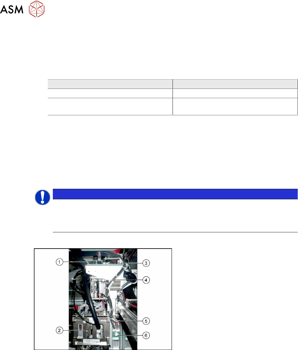
Overview
Fig.133: Overview
1. Vision Head Interface
2. Placement head on gantry
3. Head interface
4. Cable from temperature sensor and in-
cremental encoder X axis to head inter-
face
5. The X axis incremental encoder
6. Temperature sensor
6 Gantries
6.3 X and Y axis
Service Manual SIPLACE X-Series S (from Hxxxx) 01/2021 107
Removal
► Switch off the machine, disconnect it from the power supply and secure it to prevent
unauthorized reactivation.
1.2 "Preparatory work..." [}16]
NOTICE
Recommendation
► We recommend that you always perform the following tasks from the opposite side,
over the other gantry. You may need to use a stepladder or something similar to help
you.
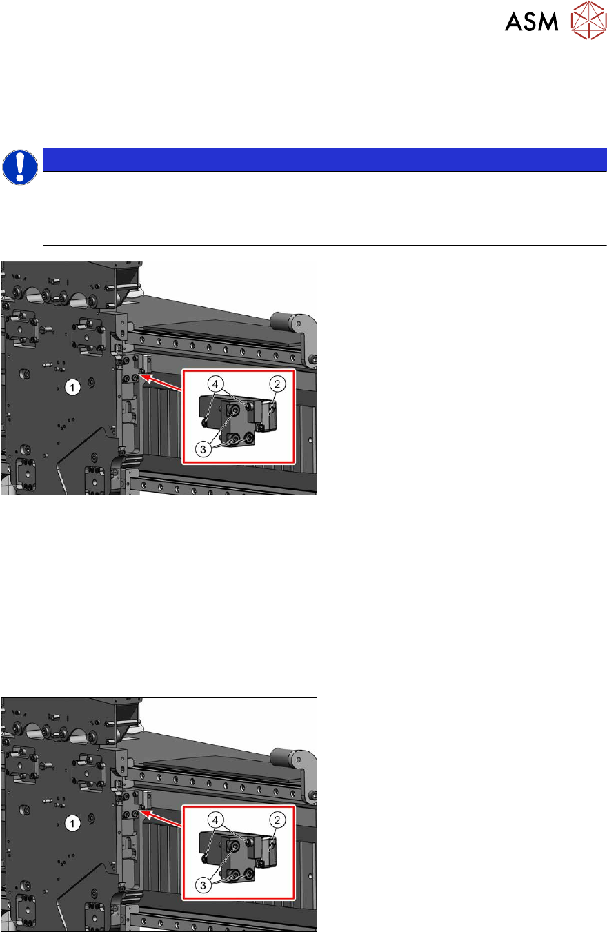
Fig.134: Removing the incremental encoder
1. Head plate
2. Incremental encoder
3. Three screws fixing the bracket to the
head plate
4. Two screws fixing the incremental en-
coder to the bracket
► Unplug the incremental encoder cable from the head interface. In this case make a note of the
position to make clear assignment easier later on.
► Unthread the connection cable as far as the incremental encoder (2).
► Remove the three screws(3) fastening the bracket to the head plate. Carefully remove the
bracket with the incremental encoder fixed to it.
► Remove the two screws(4) fastening the incremental encoder to the bracket. Remove the in-
cremental encoder from the bracket.
Installation
Fig.135: Fitting the incremental encoder
► Clean the reading surface of the incre-
mental encoder with a cloth and eth-
anol or with a cleansing tip.
► Fasten the incremental encoder(2) to
the bracket using two screws (Loctite
).
► Loosely fasten the bracket and incre-
mental encoder on it to the head plate,
using the three screws(3)
(Loctite).