00198829-01_SM_X-Series-S_Hxxxx_EN.pdf - 第108页
6 Gantries 6.3 X and Y axis 108 Service Manual SIPLACE X-Series S (from Hxxxx) 01/2021 Fig.136: Casting marks on the incremental encoder The incremental encoder must be aligned with a gap of 0.4mm (golden scale) or 0.7…
6 Gantries
6.3 X and Y axis
Service Manual SIPLACE X-Series S (from Hxxxx) 01/2021 107
Removal
► Switch off the machine, disconnect it from the power supply and secure it to prevent
unauthorized reactivation.
1.2 "Preparatory work..." [}16]
NOTICE
Recommendation
► We recommend that you always perform the following tasks from the opposite side,
over the other gantry. You may need to use a stepladder or something similar to help
you.
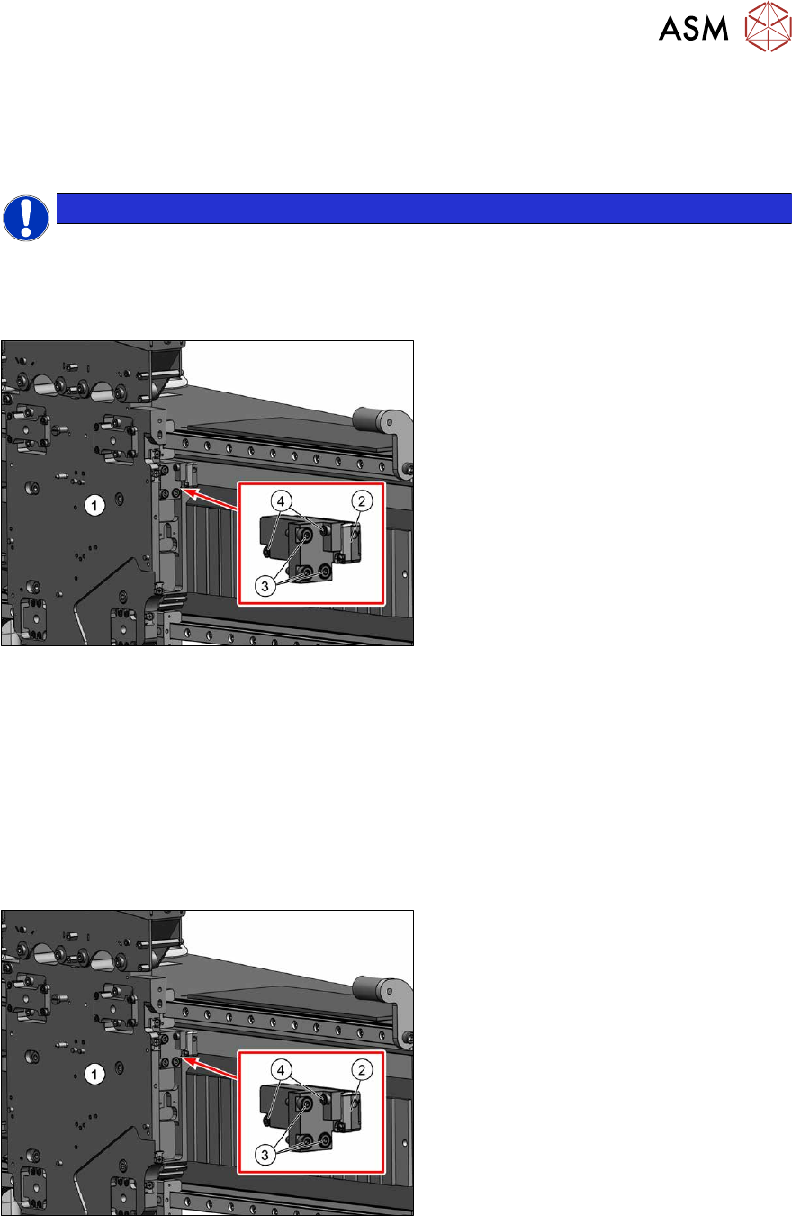
Fig.134: Removing the incremental encoder
1. Head plate
2. Incremental encoder
3. Three screws fixing the bracket to the
head plate
4. Two screws fixing the incremental en-
coder to the bracket
► Unplug the incremental encoder cable from the head interface. In this case make a note of the
position to make clear assignment easier later on.
► Unthread the connection cable as far as the incremental encoder (2).
► Remove the three screws(3) fastening the bracket to the head plate. Carefully remove the
bracket with the incremental encoder fixed to it.
► Remove the two screws(4) fastening the incremental encoder to the bracket. Remove the in-
cremental encoder from the bracket.
Installation
Fig.135: Fitting the incremental encoder
► Clean the reading surface of the incre-
mental encoder with a cloth and eth-
anol or with a cleansing tip.
► Fasten the incremental encoder(2) to
the bracket using two screws (Loctite
).
► Loosely fasten the bracket and incre-
mental encoder on it to the head plate,
using the three screws(3)
(Loctite).
6 Gantries
6.3 X and Y axis
108 Service Manual SIPLACE X-Series S (from Hxxxx) 01/2021
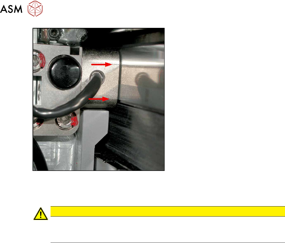
Fig.136: Casting marks on the incremental encoder
The incremental encoder must be aligned
with a gap of 0.4mm
(golden scale) or
0.75mm
(black-white scale) to the scale.
Use the corresponding thickness gauge
(plastic).
► Align the incremental encoder. Pay at-
tention to the following points:
– Set the exact height of the scale.
– Align the incremental encoder, us-
ing the two casting marks (arrows)
,
which mark the read area.
– Align the incremental encoder paral-
lel to the scale. The gap at the top
and bottom must be the same size.
► Tighten the fastening screws.
► Reconnect to the electricity supply (connector X14 or X15 on head interface).
CAUTION
Check how the cables are run!
► Make sure that the axes can be moved without damaging the cables.
► Fasten the cables with cable ties.
► Move the gantry into the end stopper and check that the buffer does not come into contact
with the cable.
► Check the track signals with the test device (see 6.3.4 "Track Signals and Zero
Pulse" [}111]).
6 Gantries
6.3 X and Y axis
Service Manual SIPLACE X-Series S (from Hxxxx) 01/2021 109
6.3.2 Replacing the Y axis incremental encoder
Parts, equipment and tools
●
Select the correct incremental encoder:
Machine Incremental encoder (read head)
SIPLACE X4i S, X4 S, X3 S, X2 S MS22/25 Y axis [03094996‑xx] (including plastic
thickness gauge)
SIPLACE X4i S micron, X4 S micron
SIPLACE CA PLP
MS30 Y axis [03102065‑xx]
●
If needed, mounting bracket for Y axis sensor [03086842-xx]
●
For MS22/25 incremental encoder: test device PG1-I [03102699‑xx]
●
For MS20/30/35 incremental encoder: test device PG-U [03071361‑xx] from FS02 (see also
technical information "Checking the track signals at the X and Y axes" [DE:TI2019‑02D04]
[EN:TI2019‑02E04])
●
Ethanol
Isopropanol – IPA can be used as an alternative.
Overview
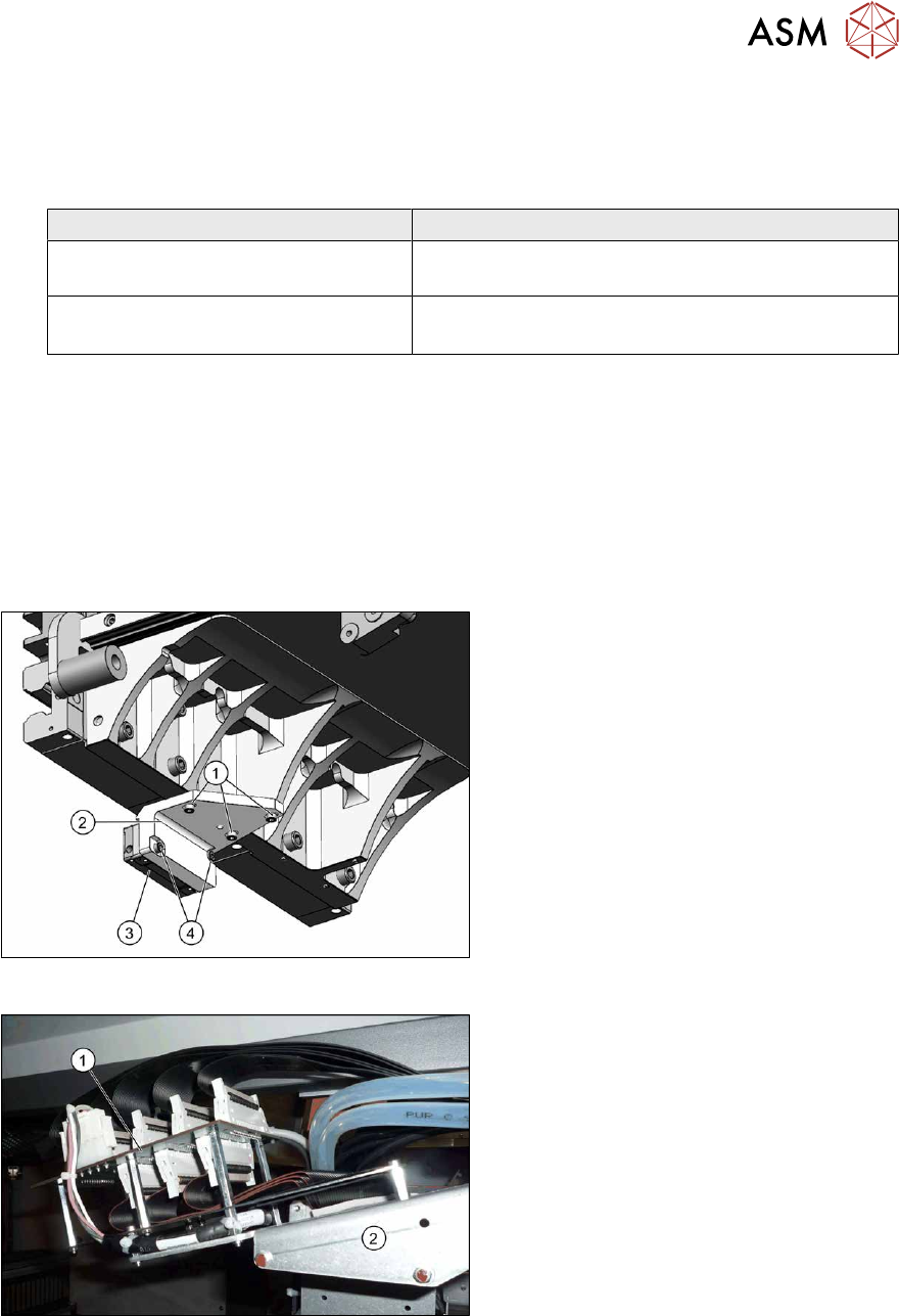
Fig.137: Overview of incremental encoder
1. Fastening screws (3x) for holder
2. Holder
3. Incremental encoder
4. Screws (2x) fastening the incremental
encoder
Fig.138: Overview of gantry interface
1. Gantry interface
2. Trailing cable holder on gantry