00198829-01_SM_X-Series-S_Hxxxx_EN.pdf - 第112页
6 Gantries 6.3 X and Y axis 112 Service Manual SIPLACE X-Series S (from Hxxxx) 01/2021 6.3.4.1 Test device – operation ► 6.3.4.1.1 "Test device PG1-I [03102699‑xx]" [ } 112] ► 6.3.4.1.2 "Test device PG-U …
6 Gantries
6.3 X and Y axis
Service Manual SIPLACE X-Series S (from Hxxxx) 01/2021 111
6.3.4 Track Signals and Zero Pulse
Equipment and tools
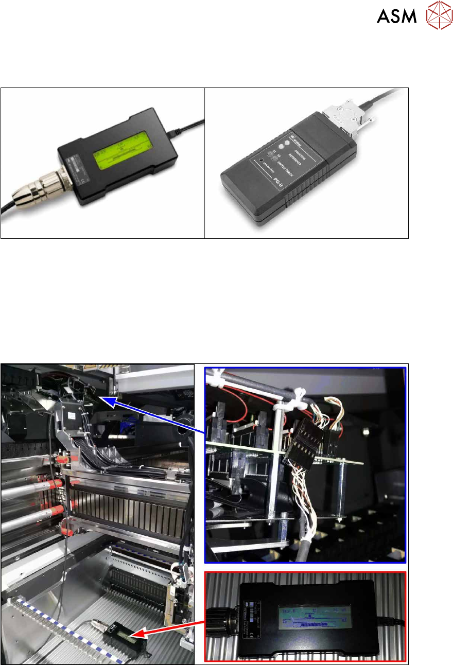
Fig.139: Test devices PG1-I and PG-U
Select the testing device suitable for your incremental encoder:
●
For MS22/25 incremental encoder: test device PG1-I [03102699‑xx]
●
For MS20/30/35 incremental encoder: test device PG-U [03071361‑xx]
Checks
Proceed as follows to check the zero pulse:
► Switch off the machine.
Fig.140: Test device
► Unplug the incremental encoder from the head interface or the gantry interface and connect it
to the test device (see also 6.3.4.1
"Test device – operation" [}112]).
► Move the head or gantry manually back and forth. This movement enables you to read the
correct track signal progress from the test device.
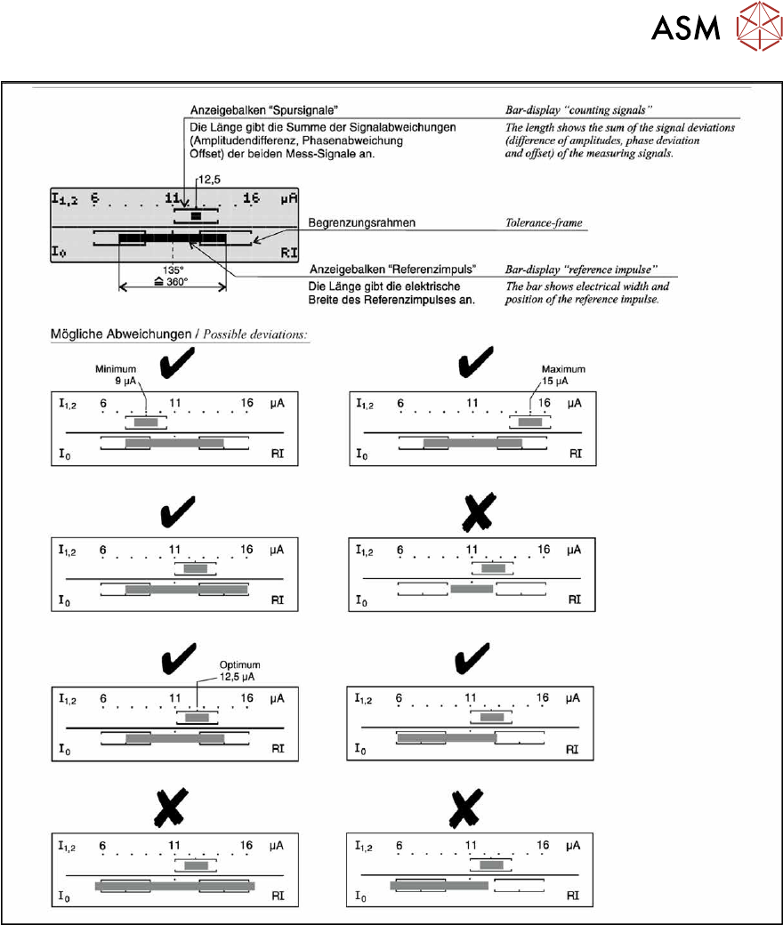
► If the track signal is not within the tolerance range, you will need to reset the incremental en-
coder. The incremental encoder has then been fitted either too near, too far away, inclined
and/or displaced.
6 Gantries
6.3 X and Y axis
Service Manual SIPLACE X-Series S (from Hxxxx) 01/2021 113
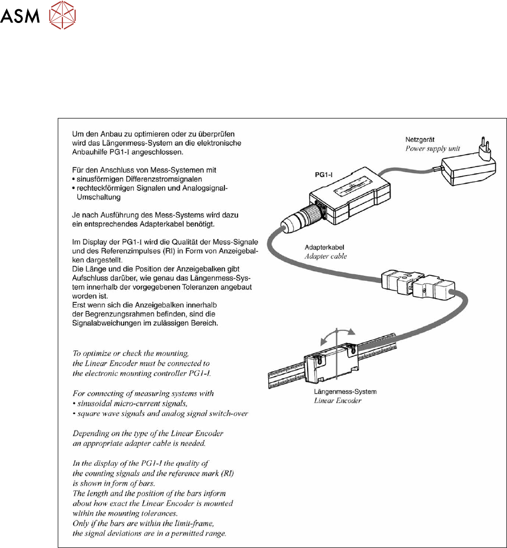
Fig.142: Operation of test device PG1-I - 2