00198829-01_SM_X-Series-S_Hxxxx_EN.pdf - 第121页
6 Gantries 6.4 Trailing cable and printed circuit boards Service Manual SIPLACE X-Series S (from Hxxxx) 01/2021 121 Fig.152: Boards on the gantry 1. Vision Head Interface (VHI) 2. Head interface 6.4.2.1 Handling the hos…
6 Gantries
6.4 Trailing cable and printed circuit boards
120 Service Manual SIPLACE X-Series S (from Hxxxx) 01/2021
Overview
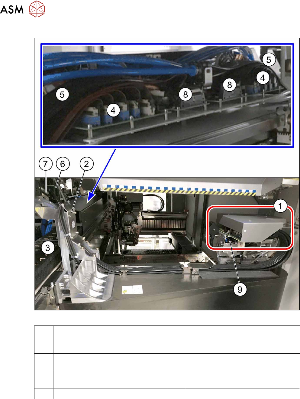
Fig.151: Overview of trailing cable
1 Boards on the gantry (under the cover,
see below)
2 Trailing cable console
3 Power track chain 4 Trailing interface gantry
5 Pneumatic hoses to the pneumatic dis-
tributor (in the machine base)
6 Gantry interface
7 Connection piece for cooling tubes to Y
motor
8 Vision Base Interface
9 Pneumatic distributor
6 Gantries
6.4 Trailing cable and printed circuit boards
Service Manual SIPLACE X-Series S (from Hxxxx) 01/2021 121
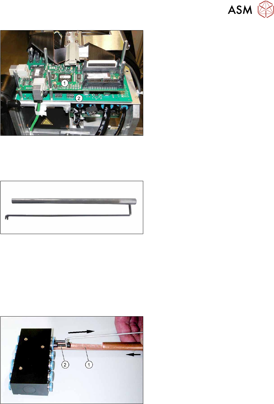
Fig.152: Boards on the gantry
1. Vision Head Interface (VHI)
2. Head interface
6.4.2.1 Handling the hose unlocking tool
Equipment and tools
Fig.153: Unlocking tool
●
Tool set vacuum connection X-Series
(unlocking tool) [03051867‑xx]
Consists of:
– Hose unlocking tool [03047090-xx]
– Unlocking tool for QSC-10H
[03051853-xx]
Usage
► Switch off the compressed air supply
5.2 "Disabling the compressed air supply" [}86]
Due to the poor access to the pneumatic distributor, we recommend using the unlocking tool.
With the help of the hose unlocking tool, you can open the unlocking ring for the compressed air
connection. This enables you to remove both the hoses and the blanking plugs (additional tool "Un-
locking tool for QSC-10H" [03051853-xx]).
Fig.154: Handling the unlocking tool
► Use the pipe-shaped tool (1) to open
the unlocking ring (blue here).
► Carefully pull the hose or the blanking
plug(2)
out of the compressed air con-
nection.
6 Gantries
6.4 Trailing cable and printed circuit boards
122 Service Manual SIPLACE X-Series S (from Hxxxx) 01/2021
6.4.2.2 Replacing the X Trailing Cable
Parts, equipment and tools
●
X trailing cable (see above)
●
Hose unlocking tool [03047090-xx]
●
Pipe/hose cutters [00381443-xx]
●
Sealing varnish Loctite 241 [02101037-xx]
●
Edding marker, white [00382740-xx]
●
Help of second person, if needed
●
Assembly instructions "Option Vacuum Pump SIPLACE X-Series S from Hxxxx " [DEEN:
00198599‑xx]
Removal
NOTICE
Vacuum pump
► When a vacuum pump is fitted, also observe the assembly instructions "Vacuum pump
X-Series S, SX4/DX4" [00196845‑xx].
► Switch off the machine, disconnect it from the power supply and secure it to prevent
unauthorized reactivation.
1.2 "Preparatory work..." [}16]
► Switch off the compressed air supply
5.2 "Disabling the compressed air supply" [}86]
Loosening the trailing cable on the machine side
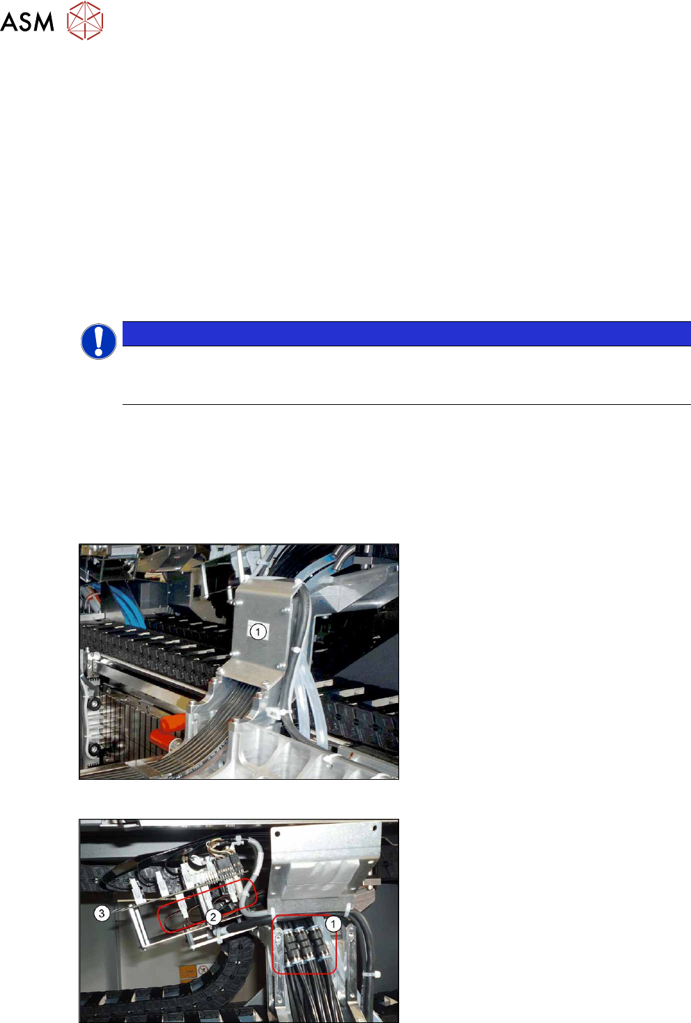
Fig.155: Dismantling the cover
► Remove the six screws fastening the
cover(1)
and remove the cover.
Fig.156: Hoses and connectors
► Mark the positions of the hoses on both
sides of the couplings(1)
, so that these
can be easily assigned later on.
► Pull the hoses off the couplings.
► Mark the positions of the connectors(2)
on the gantry interface(3), so that
these can be easily assigned later on.
► Pull the connector off the gantry inter-
face and unthread the cable.