00198829-01_SM_X-Series-S_Hxxxx_EN.pdf - 第127页
6 Gantries 6.4 Trailing cable and printed circuit boards Service Manual SIPLACE X-Series S (from Hxxxx) 01/2021 127 6.4.3 Replacing the Trailing Cable Interface Parts, equipment and tools ● Trailing cable interface gantr…
6 Gantries
6.4 Trailing cable and printed circuit boards
126 Service Manual SIPLACE X-Series S (from Hxxxx) 01/2021
Fig.163: Cable
► Dismantle the cover(1) on the trailing
cable interface(2)
.
► Mark the cables coming from the trail-
ing cable on the trailing cable interface,
to make clear assignment easier later
on.
► Unplug the cables coming from the
trailing cable at the trailing cable inter-
face.
► Carefully remove the trailing cable from the machine. You might need to enlist the help of a
second person.
Installation
Installation is performed by following the above instructions in the reverse order. Also observe the
following instructions:
► Clean the trailing cable contact surface on the machine base with a dry cloth.
► Always handle the new trailing cable with care.
► Make sure that the flat ribbon cable and the pneumatic hoses are not rubbed against any
parts or folded. Look out for sharp edges.
► Prepare the trailing cable. Place the old and new trailing cables next to one another and
match the length of the new trailing cable hose to the old one.
► For production reasons, the new trailing cable is supplied with a holder. This new holder can
be dismantled before installation and the holder already in the machine can be used again.
If you use the new holder, you will need to dismantle all attached items (boards etc.) from the
old holder and attach them to the new holder.
► Carefully insert the new trailing cable into the prescribed position. Make sure you do not fold
or twist the trailing cable.
► Check that the power track chain runs parallel to the machine base. Move the gantry back and
forth.
► If it is difficult to push the hoses onto the tubes, moisten these first with isopropanol.
► Secure all screws with Loctite 241.
6 Gantries
6.4 Trailing cable and printed circuit boards
Service Manual SIPLACE X-Series S (from Hxxxx) 01/2021 127
6.4.3 Replacing the Trailing Cable Interface
Parts, equipment and tools
●
Trailing cable interface gantry 2 and 4 assembly [03071356-xx] or
●
Trailing cable interface gantry 1 and 3 assembly [03071355-xx]
NOTICE
Machines from serial number Hxxxx
From series no. Hxxxx the trailing interface must have at least FS02.
Overview
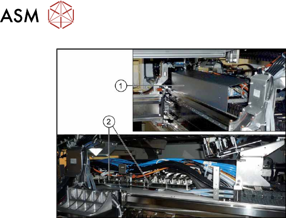
Fig.164: Overview of circuit boards
1. Cover on the trailing cable interface
2. Vision Base Interface
3. Trailing unit interface
Removal
► Switch off the machine, disconnect it from the power supply and secure it to prevent
unauthorized reactivation.
1.2 "Preparatory work..." [}16]
► Remove the screws fastening the cover on the trailing cable interface and remove the cover.
► Unplug the electrical connections to the trailing interface. You may want to mark the positions
of these connections to make clear assignment easier later on.
► Remove the screws fastening the trailing interface and remove the interface from the
machine.
Installation
► Follow the removal instructions in reverse order for installation.
6 Gantries
6.4 Trailing cable and printed circuit boards
128 Service Manual SIPLACE X-Series S (from Hxxxx) 01/2021
6.4.4 Replacing the Vision Base Interface (VBI)
Parts, equipment and tools
Fig.165: Vision Base Interface (VBI) [03115474‑xx]
●
Vision Base Interface (VBI) [03115474‑xx]
Overview
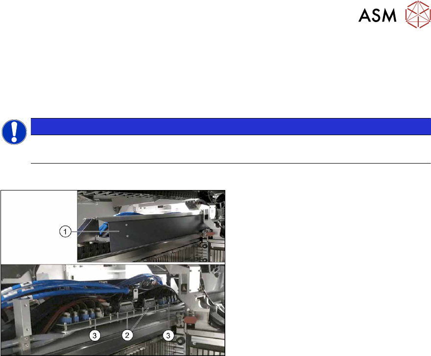
Fig.166: Overview of circuit boards
1. Cover on the trailing cable interface
2. Vision Base Interface
3. Trailing unit interface
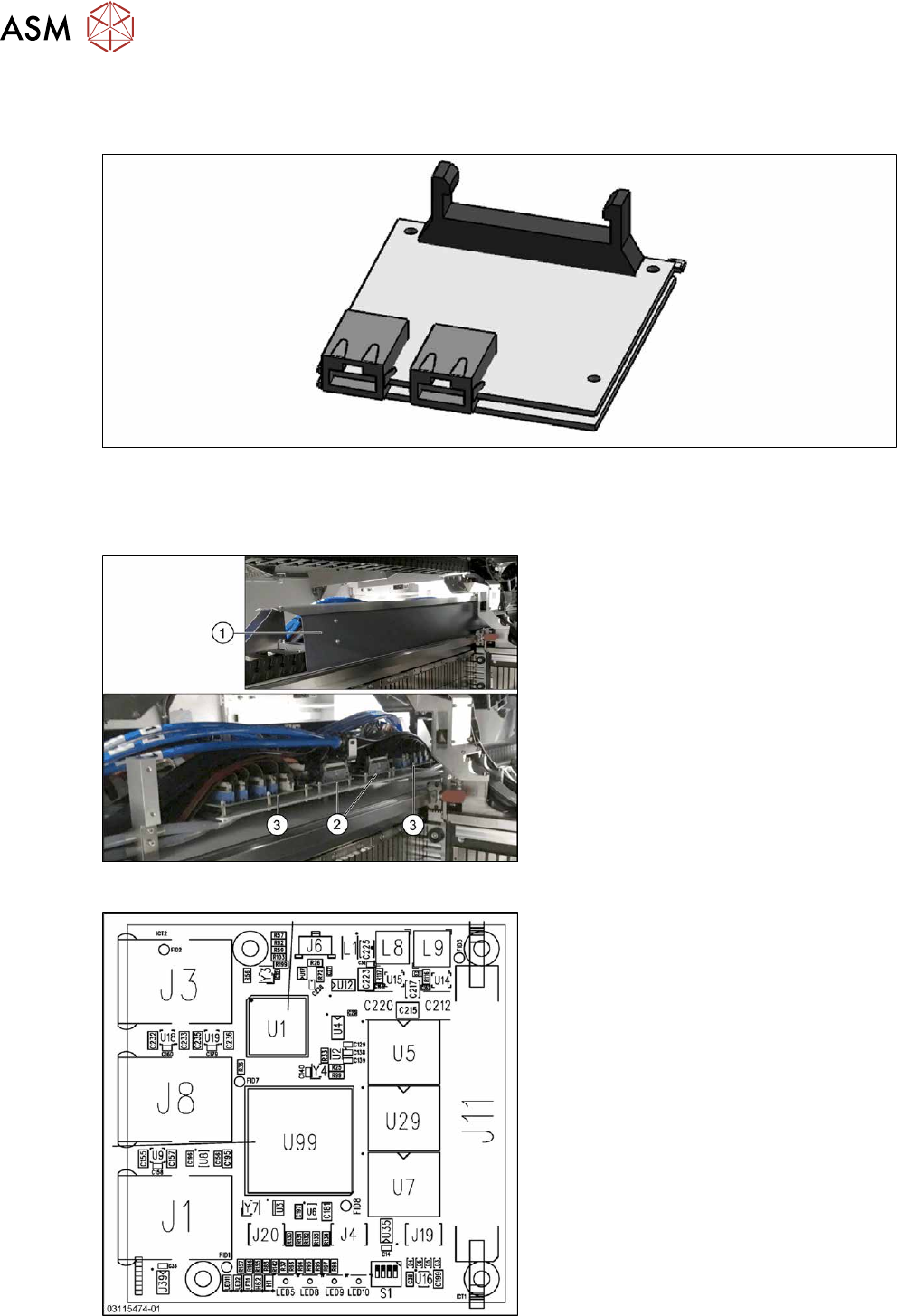
Fig.167: Vision Base Interface [03115474-xx]
The Vision Base Interface [03115474‑xx] is
fitted next to the trailing cable interface.
J1: Not used and not placed
J3: BoxPC
J4: Not used
J6: Power supply
J8: Stationary camera
J11: Trailing cable (head)
J19: Not used
J20: Not used