00198829-01_SM_X-Series-S_Hxxxx_EN.pdf - 第130页
6 Gantries 6.4 Trailing cable and printed circuit boards 130 Service Manual SIPLACE X-Series S (from Hxxxx) 01/2021 Fig.170: Gantry interface [03089221-03] Gantry interface [03089221-03]: This gantry interface is used a…
6 Gantries
6.4 Trailing cable and printed circuit boards
Service Manual SIPLACE X-Series S (from Hxxxx) 01/2021 129
Removal/installation
► Removal and installation of the Vision Base Interface (VBI) is the same as that for the trailing
cable interface. Please read section 6.4.3
"Replacing the Trailing Cable Interface" [}127].
► Checking the embedded software and performing a download if needed (see LINK).
10.1 "eSW Download (SW 70x)" [}379]
6.4.5 Replacing the gantry interface
Parts, equipment and tools
●
Gantry interface gantry 1 and 3 SX4a [03089220-xx]
●
Gantry interface gantry 2 and 4 SX4a [03089221-xx]
NOTICE
Machines from Serial Number Hxxxx
The gantry interface version used for machines from serial number Hxxxx must be at least -03.
Overview
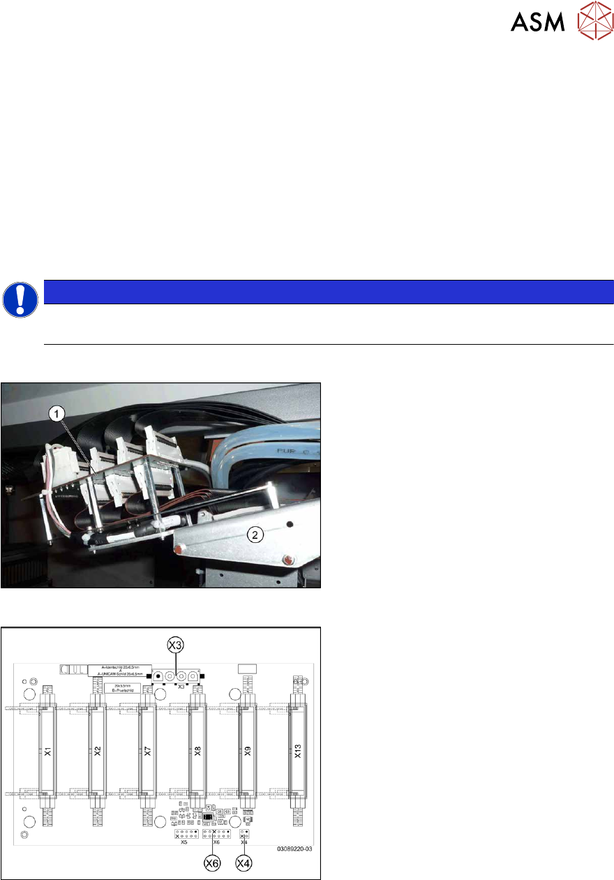
Fig.168: Gantry interface
1. Gantry interface
2. Trailing cable holder on gantry
Fig.169: Gantry interface [03089220-03]
Gantry interface [03089220-03]:
This gantry interface is used at gantries 1
and 3.
X3) Y axis motor power
X4) Y axis motor temperature sensor
X6) Y axis incremental encoder
6 Gantries
6.4 Trailing cable and printed circuit boards
130 Service Manual SIPLACE X-Series S (from Hxxxx) 01/2021
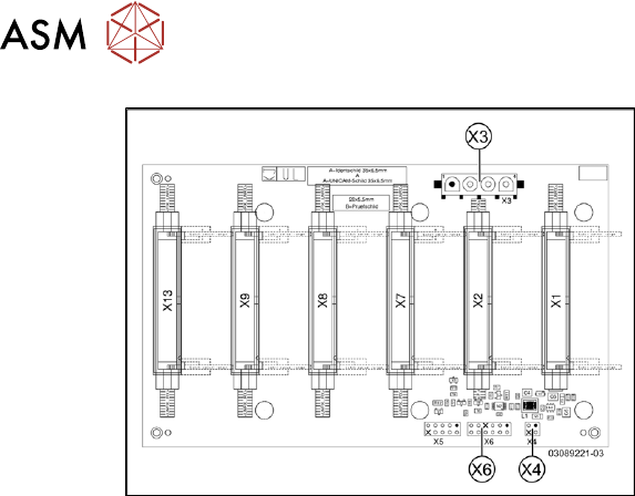
Fig.170: Gantry interface [03089221-03]
Gantry interface [03089221-03]:
This gantry interface is used at gantries 2
and 4.
X3) Y axis motor power
X4) Y axis motor temperature sensor
X6) Y axis incremental encoder
Removal
► Switch off the machine, disconnect it from the power supply and secure it to prevent
unauthorized reactivation.
1.2 "Preparatory work..." [}16]
► Unplug all electrical connections to the gantry interface. You may want to mark the positions
of these connections to make clear assignment easier later on.
► Remove the screws fastening the gantry interface and remove the gantry interface from the
machine.
Installation
Follow the removal instructions in reverse order for installation.
6 Gantries
6.4 Trailing cable and printed circuit boards
Service Manual SIPLACE X-Series S (from Hxxxx) 01/2021 131
6.4.6 Replacing the Head Interface
Parts, equipment and tools
NOTICE
SIPLACE C&P20 P/P2
If converting to a SIPLACE C&P20 P/P2, you must fulfil the following requirements:
► The head interface must have at least FS03 for a SIPLACE C&P20 P and at least
FS04 for a SIPLACE C&P20 P2.
► The Powercube [03055514-xx] must have at least FS02. Head interface with FS03 or
higher fulfil this requirement.
► It is possible to use a SIPLACE C&P20 P2 from serial no. H1440.
► A combination of SIPLACE C&P20 P and SIPLACE C&P20 P2 is not possible.
●
Select the appropriate head interface:
Machine type Gantry Head interface
SIPLACE X3 S, X4 S (micron) All Module head interface C700X-L HR
[03091013‑xx]
SIPLACE X4i S (micron) 1 and 3
SIPLACE X4i S (micron) 2 and 4 (rotated) Module head interface C700X-R HR
[03091023‑xx]
●
Loctite 241 or 243
Overview
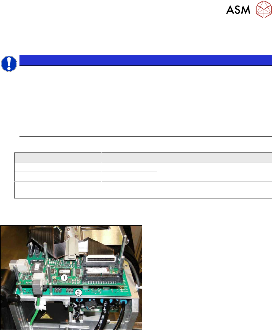
Fig.171: Boards on the gantry (from Hxxxx, with GigE)
1. Vision Head Interface (VHI)
2. Head interface including power cube
(under the VHI)