00198829-01_SM_X-Series-S_Hxxxx_EN.pdf - 第133页
6 Gantries 6.4 Trailing cable and printed circuit boards Service Manual SIPLACE X-Series S (from Hxxxx) 01/2021 133 Board description for head interface C700X-L/R HR There are two head interface designs. Depending on the…
6 Gantries
6.4 Trailing cable and printed circuit boards
132 Service Manual SIPLACE X-Series S (from Hxxxx) 01/2021
Removal
► Switch off the machine, disconnect it from the power supply and secure it to prevent
unauthorized reactivation.
1.2 "Preparatory work..." [}16]
► If there is a cover above the boards, dismantle it.
6.4.1 "Replacing the cover on the boards" [}118]
► Dismantle the Vision Head Interface.
6.4.8 "Replacing the Vision head interface (VHI)" [}136]
► Unplug all connector from the head interface and remove all cable ties. You might like to mark
their positions to make clear assignment or replacement easier later on.
► Remove the screws fastening the head interface.
► Carefully remove the head interface. Make sure that the connectors to the head adapter
MHCU are not damaged.
Installation
► Apply the DIP switch setting from the old head interface.
Follow the removal instructions in reverse order for further installation. Also observe the following
instructions:
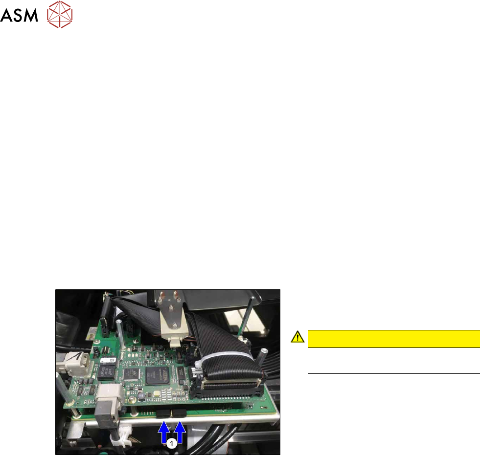
Fig.172: Dummy plug
► Secure the connector X1on the head
interface, if present, with two dummy
plugs(1)
.
CAUTION!
Without the dummy plugs, there is a
risk of short circuit at the board cover!
.
6 Gantries
6.4 Trailing cable and printed circuit boards
Service Manual SIPLACE X-Series S (from Hxxxx) 01/2021 133
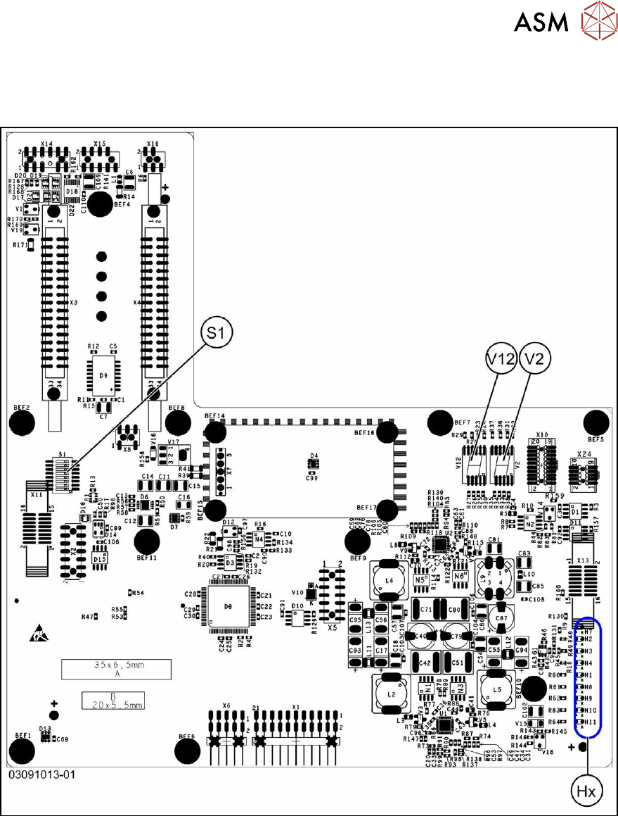
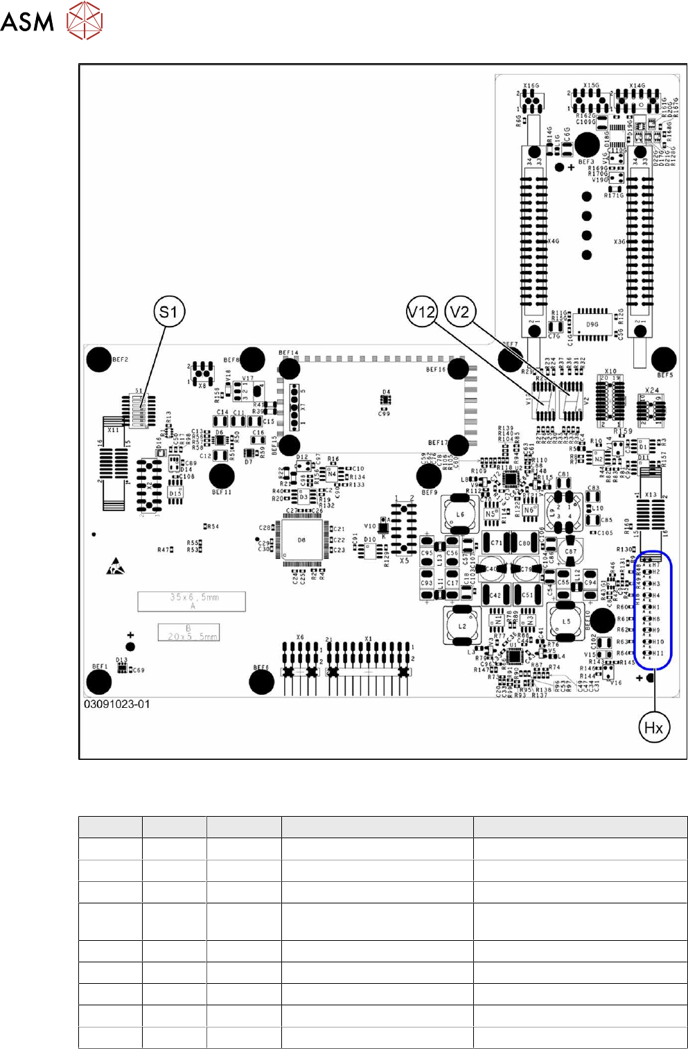
Board description for head interface C700X-L/R HR
There are two head interface designs. Depending on the gantry, either head interface C700X-L or
C700X-R will be used.
Fig.173: Standard gantry (not rotated) [03091013-01]
6 Gantries
6.4 Trailing cable and printed circuit boards
134 Service Manual SIPLACE X-Series S (from Hxxxx) 01/2021
Fig.174: Rotated gantry (gantry 2 and 4 at X4i S) [03091023-01]
LEDs (Hx) [03091013-01] [03091023-01]
LED Color Status Signal name Description
H1 RD - HCU1_LED_ERROR Not used
H2 RD ON POWERFAIL_BASE PowerFail from power supply
H3 RD ON EMERGENCY-STOP_3V Emergency stop: cover opened
H4 RD ON POWERFAIL_LOCAL_3V PowerFail local: errors at 1.5V,
3.3V, 5V, +15V, -15V
H7 RD ON X_TEMP_SENS X motor: temperature too high
H8 RD - HCU2_LED_ERROR Not used
H9 RD - HCU1_LED_READY Not used
H10 RD - HCU2_LED_READY Not used
H11 GN ON LED_5V_OK FPGA OK