00198829-01_SM_X-Series-S_Hxxxx_EN.pdf - 第134页
6 Gantries 6.4 Trailing cable and printed circuit boards 134 Service Manual SIPLACE X-Series S (from Hxxxx) 01/2021 Fig.174: Rotated gantry (gantry 2 and 4 at X4i S) [03091023-01] LEDs (Hx) [03091013-01] [03091023-01] L…
6 Gantries
6.4 Trailing cable and printed circuit boards
Service Manual SIPLACE X-Series S (from Hxxxx) 01/2021 133
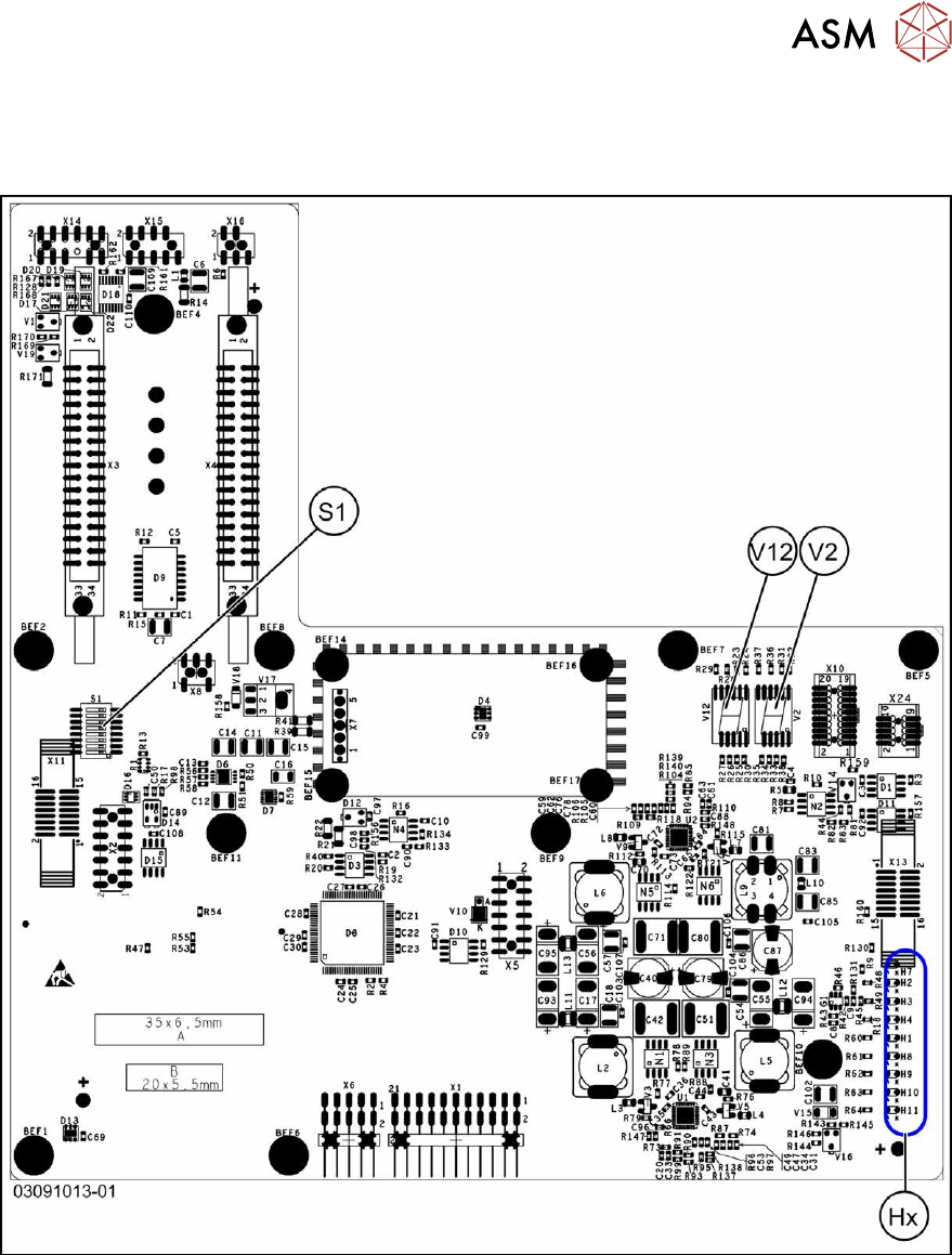
Board description for head interface C700X-L/R HR
There are two head interface designs. Depending on the gantry, either head interface C700X-L or
C700X-R will be used.
Fig.173: Standard gantry (not rotated) [03091013-01]
6 Gantries
6.4 Trailing cable and printed circuit boards
134 Service Manual SIPLACE X-Series S (from Hxxxx) 01/2021
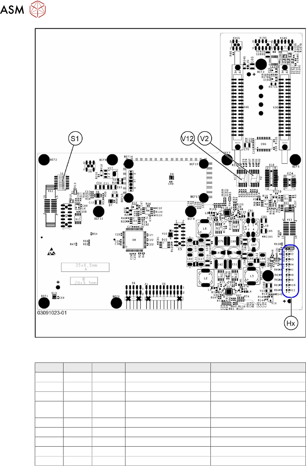
Fig.174: Rotated gantry (gantry 2 and 4 at X4i S) [03091023-01]
LEDs (Hx) [03091013-01] [03091023-01]
LED Color Status Signal name Description
H1 RD - HCU1_LED_ERROR Not used
H2 RD ON POWERFAIL_BASE PowerFail from power supply
H3 RD ON EMERGENCY-STOP_3V Emergency stop: cover opened
H4 RD ON POWERFAIL_LOCAL_3V PowerFail local: errors at 1.5V,
3.3V, 5V, +15V, -15V
H7 RD ON X_TEMP_SENS X motor: temperature too high
H8 RD - HCU2_LED_ERROR Not used
H9 RD - HCU1_LED_READY Not used
H10 RD - HCU2_LED_READY Not used
H11 GN ON LED_5V_OK FPGA OK
6 Gantries
6.4 Trailing cable and printed circuit boards
Service Manual SIPLACE X-Series S (from Hxxxx) 01/2021 135
7-segment display V2 [03091013-01] [03091023-01]
Display Status Description
Decimal point Flashes HCU2 OK
7-segment display V12 [03091013-01] [03091023-01]
Display Status Description
Decimal point Flashes HCU1 OK
DIP switch S1 [03091013-01] [03091023-01]
Switch Status Signal name Description
Gantry 1 Gantry 2 Gantry 3 Gantry 4
S1.1 OFF/ON Gantry_ID0 OFF ON OFF ON
S1.2 OFF/ON Gantry_ID1 OFF OFF ON ON
S1.3 OFF COM_BOOT_HCU ON: set HCU to bootstrap mode
S1.4 OFF RESET_HCU2 ON: Reset HCU2
S1.5 OFF RESET_HCU1 ON: Reset HCU1
S1.6 OFF FAN Not used
S1.7 OFF DCDC_OFF ON: Reset, when not all the voltages are present
S1.8 OFF HCU_1_2 Not used
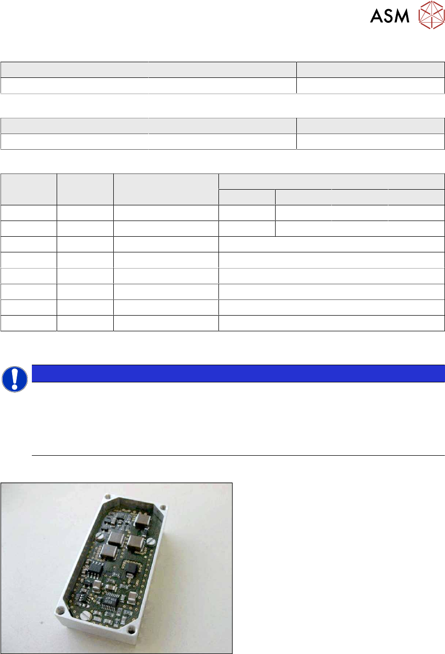
6.4.7 Replacing the power cube module on the head interface
NOTICE
SIPLACE C&P20 P/P2
The following additional conditions must be fulfilled for operating a SIPLACE C&P20P/P2:
► The module power cube must have at least function state [03055514-02].
► You find a complete list of the prerequisites in section 8.5 "Replacing the SIPLACE
C&P20P/M2" [}260].
Overview
Fig.175: Powercube module
Powercube module [03055514-xx]