00198829-01_SM_X-Series-S_Hxxxx_EN.pdf - 第135页
6 Gantries 6.4 Trailing cable and printed circuit boards Service Manual SIPLACE X-Series S (from Hxxxx) 01/2021 135 7-segment display V2 [03091013-01] [03091023-01] Display Status Description Decimal point Flashes HCU2 O…
6 Gantries
6.4 Trailing cable and printed circuit boards
134 Service Manual SIPLACE X-Series S (from Hxxxx) 01/2021
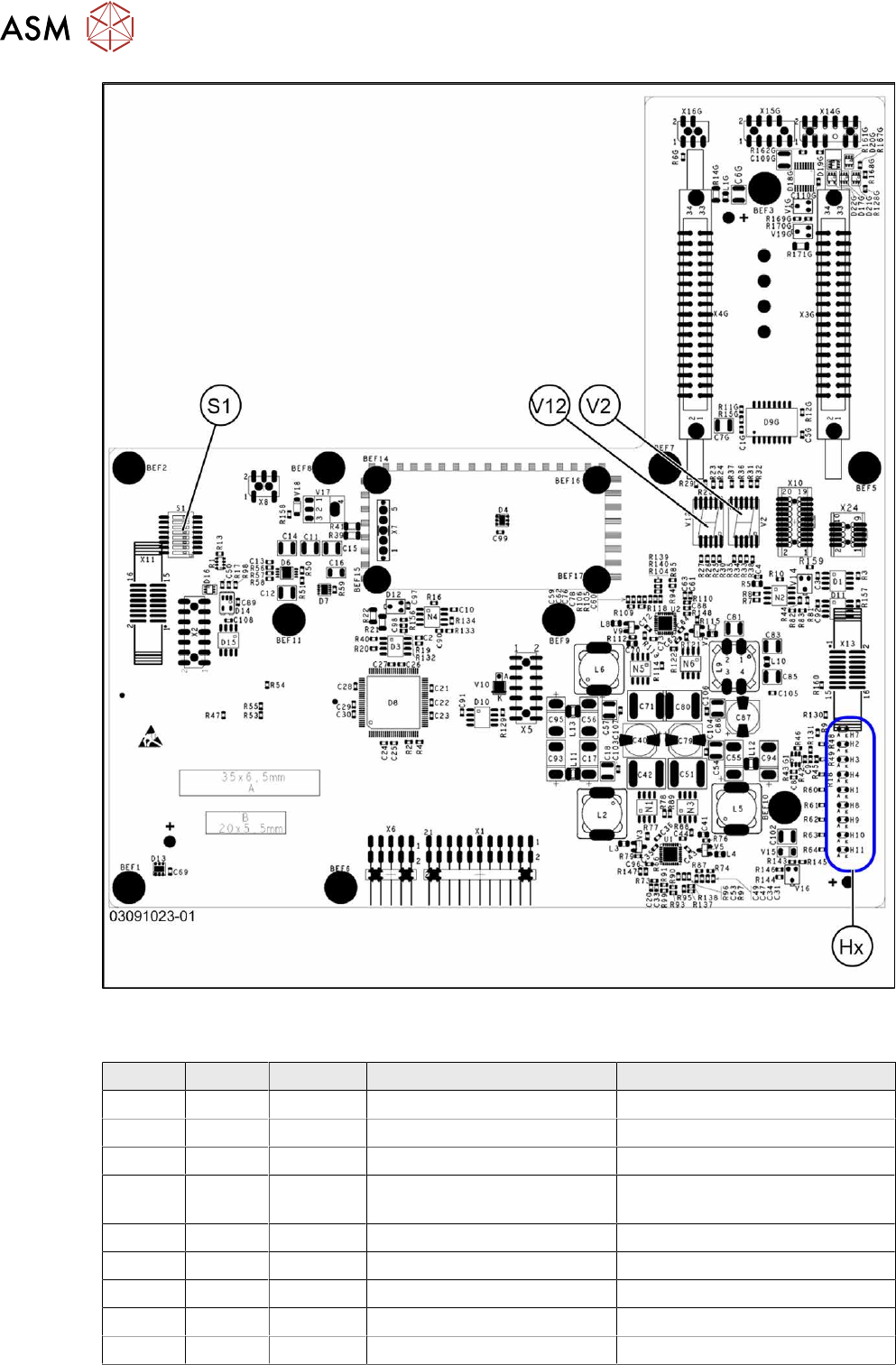
Fig.174: Rotated gantry (gantry 2 and 4 at X4i S) [03091023-01]
LEDs (Hx) [03091013-01] [03091023-01]
LED Color Status Signal name Description
H1 RD - HCU1_LED_ERROR Not used
H2 RD ON POWERFAIL_BASE PowerFail from power supply
H3 RD ON EMERGENCY-STOP_3V Emergency stop: cover opened
H4 RD ON POWERFAIL_LOCAL_3V PowerFail local: errors at 1.5V,
3.3V, 5V, +15V, -15V
H7 RD ON X_TEMP_SENS X motor: temperature too high
H8 RD - HCU2_LED_ERROR Not used
H9 RD - HCU1_LED_READY Not used
H10 RD - HCU2_LED_READY Not used
H11 GN ON LED_5V_OK FPGA OK
6 Gantries
6.4 Trailing cable and printed circuit boards
Service Manual SIPLACE X-Series S (from Hxxxx) 01/2021 135
7-segment display V2 [03091013-01] [03091023-01]
Display Status Description
Decimal point Flashes HCU2 OK
7-segment display V12 [03091013-01] [03091023-01]
Display Status Description
Decimal point Flashes HCU1 OK
DIP switch S1 [03091013-01] [03091023-01]
Switch Status Signal name Description
Gantry 1 Gantry 2 Gantry 3 Gantry 4
S1.1 OFF/ON Gantry_ID0 OFF ON OFF ON
S1.2 OFF/ON Gantry_ID1 OFF OFF ON ON
S1.3 OFF COM_BOOT_HCU ON: set HCU to bootstrap mode
S1.4 OFF RESET_HCU2 ON: Reset HCU2
S1.5 OFF RESET_HCU1 ON: Reset HCU1
S1.6 OFF FAN Not used
S1.7 OFF DCDC_OFF ON: Reset, when not all the voltages are present
S1.8 OFF HCU_1_2 Not used
6.4.7 Replacing the power cube module on the head interface
NOTICE
SIPLACE C&P20 P/P2
The following additional conditions must be fulfilled for operating a SIPLACE C&P20P/P2:
► The module power cube must have at least function state [03055514-02].
► You find a complete list of the prerequisites in section 8.5 "Replacing the SIPLACE
C&P20P/M2" [}260].
Overview
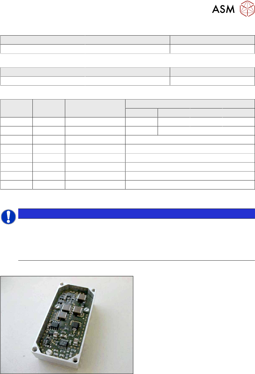
Fig.175: Powercube module
Powercube module [03055514-xx]
6 Gantries
6.4 Trailing cable and printed circuit boards
136 Service Manual SIPLACE X-Series S (from Hxxxx) 01/2021
Removal
► Switch off the machine, disconnect it from the power supply and secure it to prevent
unauthorized reactivation.
1.2 "Preparatory work..." [}16]
► Dismantle the head interface
6.4.6 "Replacing the Head Interface" [}131]
► Remove the four screws fastening the power cube and carefully lift off the power cube from
the head interface.
Installation
Follow the removal instructions in reverse order for installation. Observe the following note:
► Make sure that the power cube is positioned correctly.
6.4.8 Replacing the Vision head interface (VHI)
Parts, equipment and tools
●
Vision Head Interface (VHI) [03115454-xx]
Overview
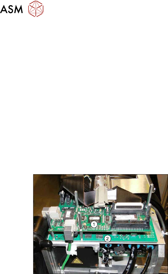
Fig.176: Boards on the gantry
1. Vision Head Interface (VHI)
2. Head interface
3. Powercube on the head interface