00198829-01_SM_X-Series-S_Hxxxx_EN.pdf - 第137页
6 Gantries 6.4 Trailing cable and printed circuit boards Service Manual SIPLACE X-Series S (from Hxxxx) 01/2021 137 Fig.177: Vision Head Interface Press-fit connections Connector Description J14 CAM1 – PCB camera J16 CA…
6 Gantries
6.4 Trailing cable and printed circuit boards
136 Service Manual SIPLACE X-Series S (from Hxxxx) 01/2021
Removal
► Switch off the machine, disconnect it from the power supply and secure it to prevent
unauthorized reactivation.
1.2 "Preparatory work..." [}16]
► Dismantle the head interface
6.4.6 "Replacing the Head Interface" [}131]
► Remove the four screws fastening the power cube and carefully lift off the power cube from
the head interface.
Installation
Follow the removal instructions in reverse order for installation. Observe the following note:
► Make sure that the power cube is positioned correctly.
6.4.8 Replacing the Vision head interface (VHI)
Parts, equipment and tools
●
Vision Head Interface (VHI) [03115454-xx]
Overview
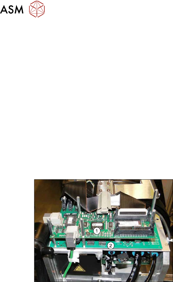
Fig.176: Boards on the gantry
1. Vision Head Interface (VHI)
2. Head interface
3. Powercube on the head interface
6 Gantries
6.4 Trailing cable and printed circuit boards
Service Manual SIPLACE X-Series S (from Hxxxx) 01/2021 137
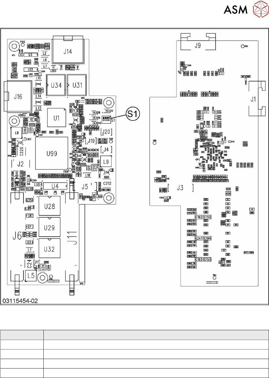
Fig.177: Vision Head Interface
Press-fit connections
Connector Description
J14 CAM1 – PCB camera
J16 CAM2 – component camera
J6, J11 Trailing cable
J5 Power supply
6 Gantries
6.4 Trailing cable and printed circuit boards
138 Service Manual SIPLACE X-Series S (from Hxxxx) 01/2021
DIP switch S1
The DIP S1 switch settings depend on the board version:
Dip switch S1 [03115454-01]
ON OFF Comments
1 ON Spread OFF/ON
2 See text X-Series S: ON
All other machines: OFF
3 See text X-Series S: OFF
All other machines: ON
4 OFF CAN-R ON/OFF
DIP switch S1 [03115454-02 und -03]
ON OFF Comments
1 See text X-Series S: OFF
All other machines: ON
2 OFF Reserve
3 ON EEPROM
4 OFF CAN-R ON/OFF
Removal
► Switch off the machine, disconnect it from the power supply and secure it to prevent
unauthorized reactivation.
1.2 "Preparatory work..." [}16]
► If there is a cover above the boards, dismantle it.
6.4.1 "Replacing the cover on the boards" [}118]
► Unplug all electrical connections to the VHI. You may want to mark the positions of these con-
nections to make clear assignment easier later on.
► Remove the screws fastening the VHI and then remove the board.
Installation
Follow the removal instructions in reverse order for installation. Also observe the following instruc-
tions:
► Set the correct gantry ID. Take the setting from the dismantled board.
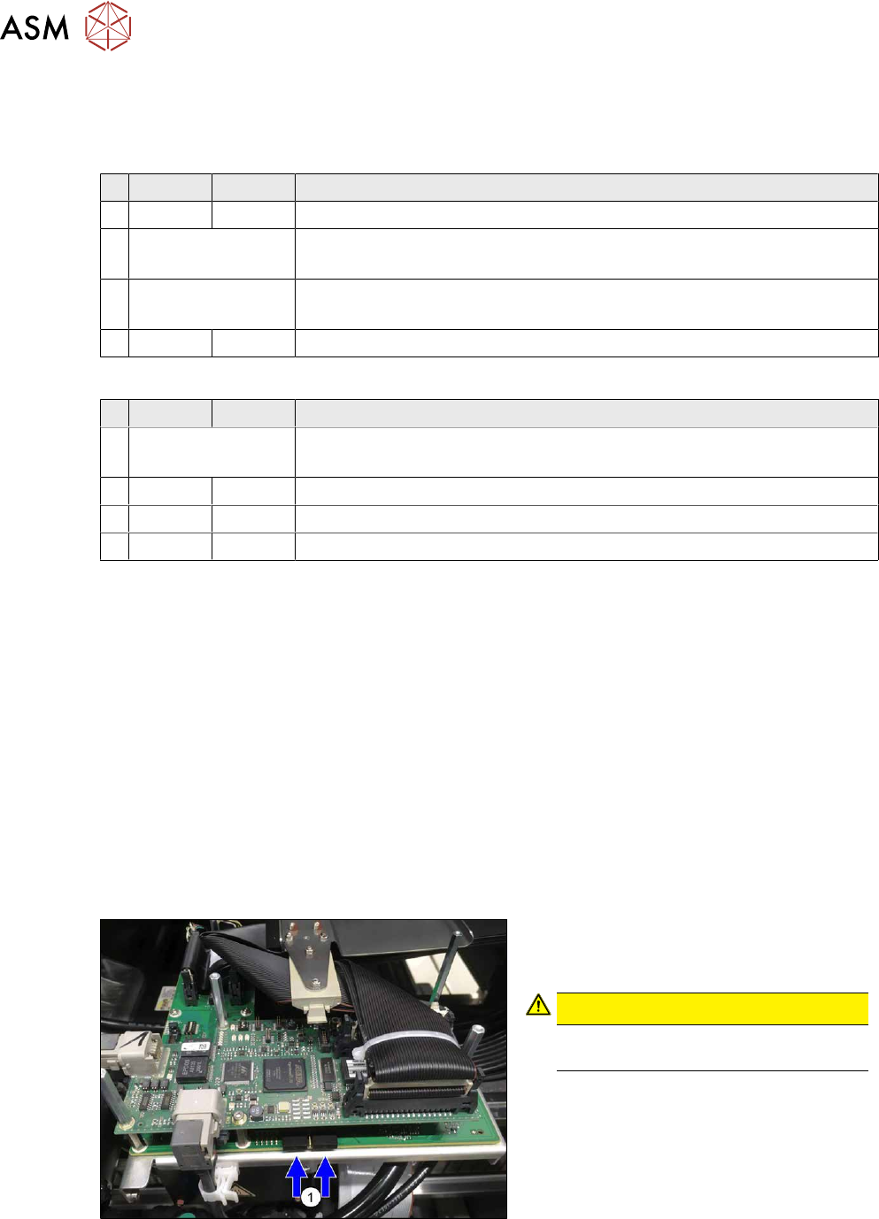
Fig.178: Dummy plug
► Secure the connector X1on the head
interface, if present, with two dummy
plugs(1)
.
CAUTION!
Without the dummy plugs, there is a
risk of short circuit at the board cover!
.
► Checking the embedded software and performing a download if needed (see LINK).
10.1 "eSW Download (SW 70x)" [}379]