00198829-01_SM_X-Series-S_Hxxxx_EN.pdf - 第151页
6 Gantries 6.6 MHCU, boards and camera Service Manual SIPLACE X-Series S (from Hxxxx) 01/2021 151 6.6.4 Replacing the connection cable from the Twin module to the basic adapter Parts, equipment and tools ● Cable / X conn…
6 Gantries
6.6 MHCU, boards and camera
150 Service Manual SIPLACE X-Series S (from Hxxxx) 01/2021
6.6.3 X Base adapter Twin
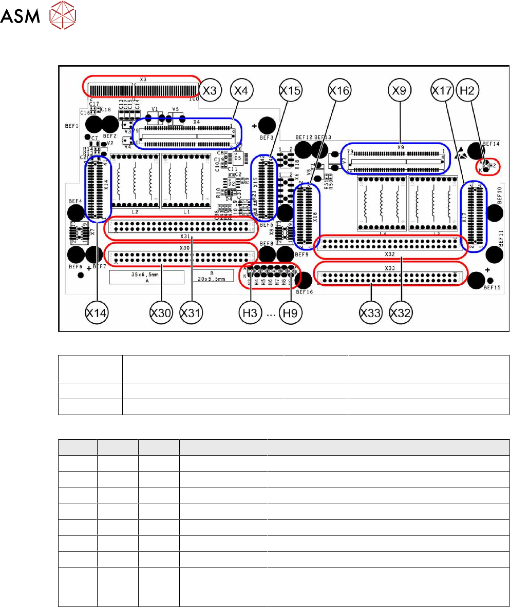
Fig.193: X base adapter Twin [03062201-03]
X4 X14 X15 Connection for MHCU (Twin mod-
ule2)
X9 X16 X17 Connection for MHCU (Twin mod-
ule1)
X30 X31 Connections for Twin module 2 X32 X33 Connections for Twin module 1
X3 Connection on the head interface H2 to H9 LEDs (see below)
LED [03054879-03]
LED Color Status Signal name Description
H2 GN ON - HMCU2 programming connector connected
H3 RD ON FPGA_TEST_6 1.5VDC PowerFail
H4 RD ON FPGA_TEST_2 3.3VDC PowerFail
H5 RD ON FPGA_TEST_4 5VDC PowerFail
H6 RD ON FPGA_TEST_1 15VDC PowerFail
H7 RD ON FPGA_TEST_3 DP PowerFail, not used
H8 RD ON FPGA_TEST_5 24VDC PowerFail
H9 RD ON POWER-
FAIL_LOCAL
PowerFail board:
ON, when 1.5VDC, 3.3VDC, 5VDC and 15VDC are
outside the permissible tolerance
The voltage monitors trigger as soon as the target voltage is undershot by 5%.
6 Gantries
6.6 MHCU, boards and camera
Service Manual SIPLACE X-Series S (from Hxxxx) 01/2021 151
6.6.4 Replacing the connection cable from the Twin module to the basic adapter
Parts, equipment and tools
●
Cable / X connection cable Twin [03062202-xx]
Overview
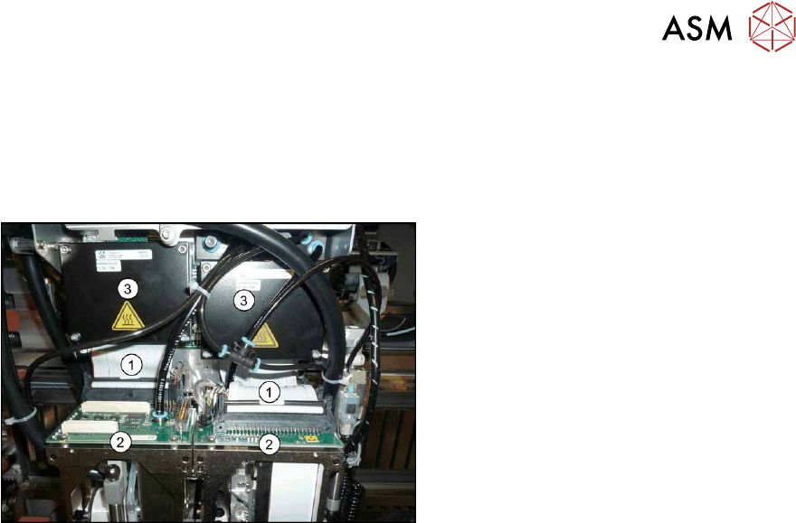
Fig.194: Cable
1. Connection cable from the Twin mod-
ule to the basic adapter
2. Twin module
3. MHCUs on the basic adapter
Removal
► Switch off the machine, disconnect it from the power supply and secure it to prevent
unauthorized reactivation.
1.2 "Preparatory work..." [}16]
► Remove the two Twin modules form the machine.
8.8
"Replacing the SIPLACE Twin" [}274]
► Remove the head adapter from the machine and then dismantle the two MHCUs.
6.6.1
"Replacing the MHCU, basic and head adapter" [}146]
► Unplug both connection cables.
Installation
Follow the removal instructions in reverse order for installation.
6 Gantries
6.6 MHCU, boards and camera
152 Service Manual SIPLACE X-Series S (from Hxxxx) 01/2021
6.6.5 Replacing the PCB Camera
Parts, equipment and tools
●
PCB camera (type 34) 28 GigE [03101402‑xx]
●
Sealing varnish Loctite 241 [02101037-xx]
Overview
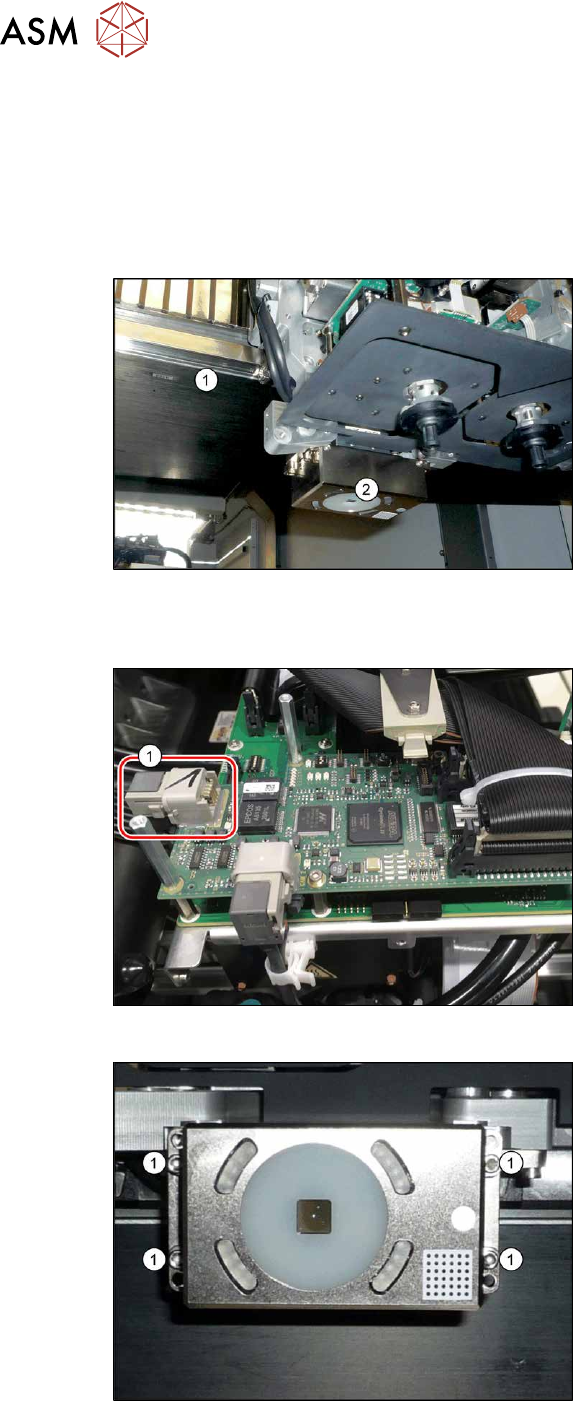
Fig.195: Overview of PCB camera
1. Gantry
2. Board camera
The PCB camera is located on the under-
side of the gantry, on the head mount.
Removal
Fig.196: Connecting cable
► Unplug the two connection cables X2
and X6(1)
and unthread these as far
as the PCB camera. You may like to
mark their positions, to make clear as-
signment easier later on.
Fig.197: PCB camera
► Remove the four screws (1) holding the
PCB camera. Mark the position to
make clear assignment easier later on.