00198829-01_SM_X-Series-S_Hxxxx_EN.pdf - 第170页
7 Conveyor 7.3 Lifting Table 170 Service Manual SIPLACE X-Series S (from Hxxxx) 01/2021 Removal CAUTION Washers The re ar e w as her s at va rio us po in ts, f or ex amp le be tw een t he li fti ng ta bl e m ot or an d t…
7 Conveyor
7.3 Lifting Table
Service Manual SIPLACE X-Series S (from Hxxxx) 01/2021 169
7.3.2 Replacing the lifting table motor
Parts, equipment and tools
●
BLDC motor BG65x50 assembly with cables and connectors [03088241-xx]
Overview
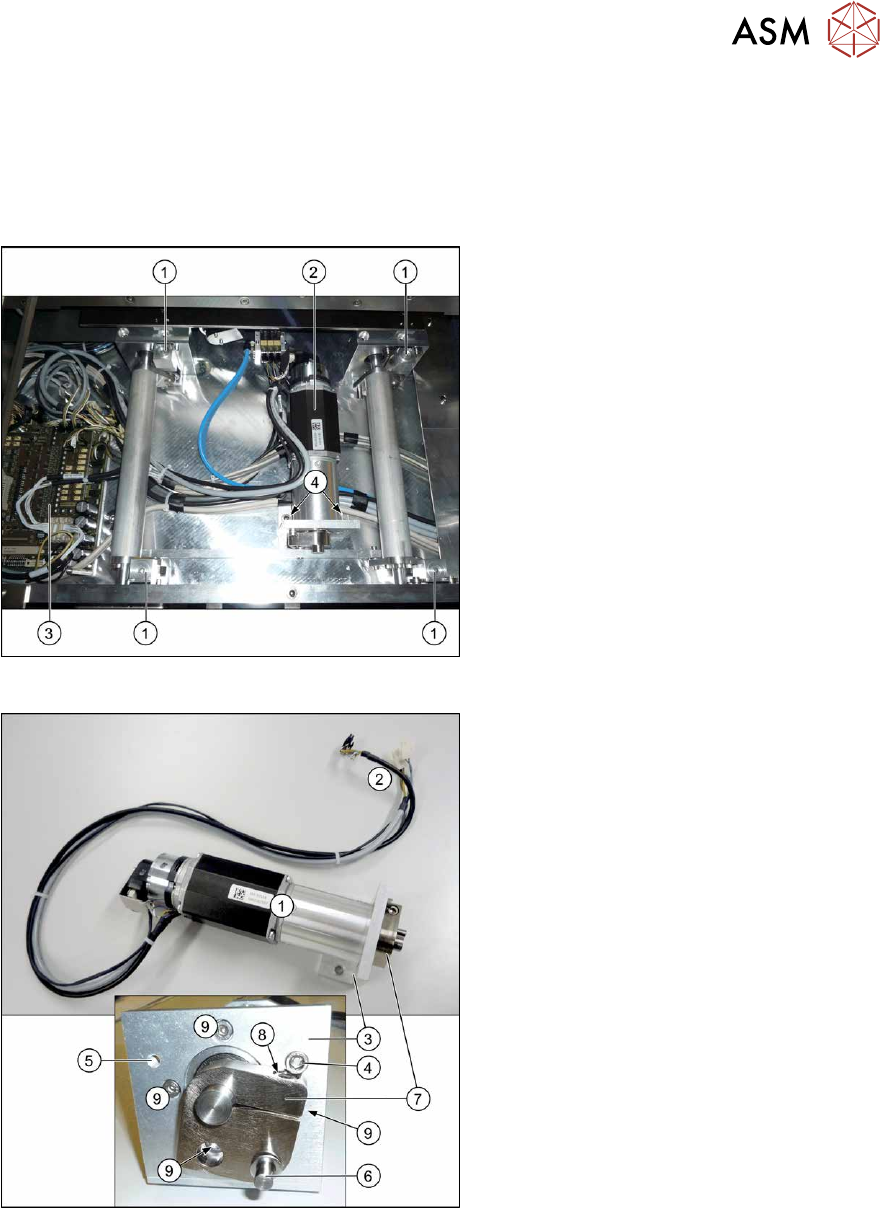
Fig.220: Lifting table when fitted
1. Lifting table plate guides
2. Lifting table motor
3. Conveyor control board
4. Screws fastening the retaining bracket
for the lifting table motor
Fig.221: Lifting table when not fitted
1. Lifting table motor
2. Electrical connections for the lifting
table motor
3. Retaining bracket for the lifting table
motor
4. Motor crank stopper for assembly in
conveyor lane 2 (left)
5. Alternative assembly position of stop-
per for assembly in conveyor lane 1
(right)
6. Connection to lifting table rods
7. Motor crank
8. Clamping screw for motor crank
9. Screws (4x) for fastening lifting table
motor to retaining bracket (partially
covered by the motor crank)
7 Conveyor
7.3 Lifting Table
170 Service Manual SIPLACE X-Series S (from Hxxxx) 01/2021
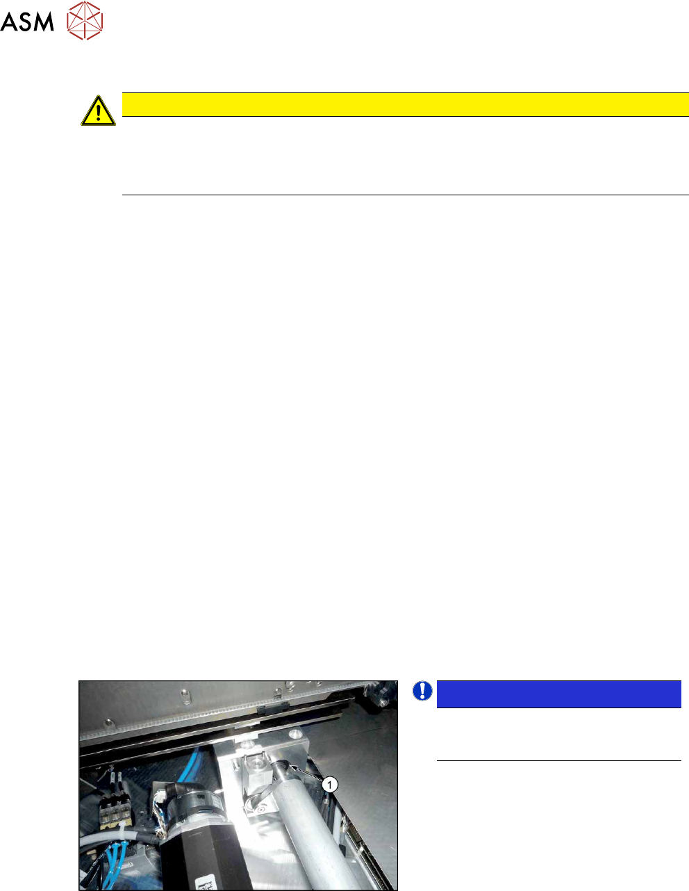
Removal
CAUTION
Washers
There are washers at various points, for example between the lifting table motor and the rods.
► Make a note of the number of washers and their positions. These will need to be fitted
again in the same places later on!
► Dismantle the lifting table plate.
7.3.1
"Replacing the lifting table plate" [}167]
► Remove the two screws fastening the fixture bracket.
► Dismantle the cover over the conveyor control board.
► Unthread the cable up to the conveyor control and then unplug it. In this case, make a note of
the positions, to make clear assignment easier later on (see also 7.9.1.1
"Conveyor control
TSP420" [}242]).
► Remove the lifting table motor from the machine.
Installation
Follow the removal instructions in reverse order for installation. Also observe the following instructions:
► The motor crank and the brackets needs to be removed and refitted on the new lifting table
motor. You may have to fit the stopper on the other side.
Use the old lifting table motor as a reference.
Observe the position and number of washers used.
► Tighten the clamping screw on the motor crank.
► Make sure that the motor connection cables do not rub against any parts.
► Set the lifting table height.
7.3.5
"Setting the Parallelism and Height of the Lifting Table Plate" [}172]
► Calibrate the lifting table motor and then perform a reference run.
7.3.4
"Calibrating the lifting table motor" [}171]
► For more information about the conveyor control refer to section 7.9.1.1 "Conveyor control
TSP420" [}242].
7.3.3 Deep-groove ball bearing on lifting table
Fig.222: Deep-groove ball bearings
NOTICE!
The deep-groove ball bearing (1) is not
a spare part for X-Series S lifting
tables.
.
7 Conveyor
7.3 Lifting Table
Service Manual SIPLACE X-Series S (from Hxxxx) 01/2021 171
7.3.4 Calibrating the lifting table motor
After completing the work on the lifting table, this will need to be calibrated.
Procedure
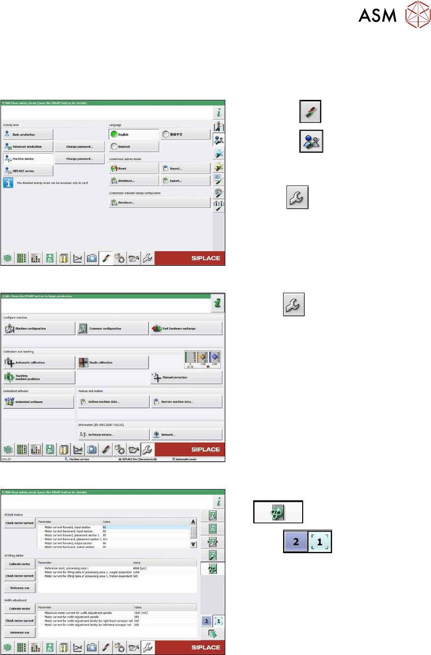
Fig.223: Select operator level
► Select the button.
► Select the button.
► Switch over to the operator level Ma-
chine service.
ð The button will be shown.
Fig.224: Service menu
► Select .
► Select Conveyor configuration.
Fig.225: Conveyor menu
► Select Initiate conveyor parameters
.
► Select to choose the re-
quired conveyor lane.
► In the relevant section, select the Cali-
brate motor button.
► Check the clamps (distance between
clamping plate and clamping rail) and
adjust if necessary.
► Check the clamps (distance between clamping plate and clamping rail) and adjust if neces-
sary.
7.3.5
"Setting the Parallelism and Height of the Lifting Table Plate" [}172]