00198829-01_SM_X-Series-S_Hxxxx_EN.pdf - 第189页
7 Conveyor 7.5 Width Adjustment, Clamps and Cylinder Unit Service Manual SIPLACE X-Series S (from Hxxxx) 01/2021 189 7.5.8 Replacing the short-stroke cylinder (width adjustment) (DC only) Parts, equipment and tools ● Com…
7 Conveyor
7.5 Width Adjustment, Clamps and Cylinder Unit
188 Service Manual SIPLACE X-Series S (from Hxxxx) 01/2021
7.5.7 Replacing the inductive sensor for side detection on the cylinder unit (width
adjustment) (DC only)
Overview
Fig.244: Proximity switch on the cylinder unit
1. Proximity switch on the cylinder unit
Proximity switch 3RG4/4.0mm/
sn=0.8mm/1S [00304908‑xx]
2. Screw fastening the proximity switch
3. Screw fastening the cylinder unit to the
carriage
See also 7.5.1 "Overview of width adjustment" [}181]
Removal
► Removal of the proximity switch is the same as that of the sensor system. Please read section
7.5.6
"Replacing the proximity switch for the cylinder unit (width adjustment) (DC
only)" [}187].
► Loosen the screw fastening the proximity switch and pull the proximity switch out of the cylin-
der unit.
Installation
Follow the removal instructions in reverse order for installation. Also observe the following instruc-
tions:
► Dismantle the connector from the old inductive sensor and fit it in the new inductive sensor.
To do this, release the crimp connections on the old inductive sensor from the connector and
insert them into the new inductive sensor. Note the correct assignment for this!
► Turn the proximity switch so that the LED is visible when fitted.
► Make sure that the proximity switch does not protrude over the basic structure of the cylinder
unit. Check this when the machine is switched on. To do this, move a conveyor side over the
cylinder unit. The LED should only shine when you do this. The gap between the conveyor
side clamping unit and the proximity switch on the cylinder unit must be at least 0.3 mm.
Check whether this gap is kept for all conveyor sides and that the proximity switch reliably re-
cognizes all conveyor sides. You can check this with the LED, when the machine is switched
on. Simply move the width adjustment manually along the whole conveyor width, with the help
of the toothed belt.
► Recalibrate all conveyor sides for lane1 and2 (both in Dual conveyor right mode and in
Dual conveyor left mode
).
7 Conveyor
7.5 Width Adjustment, Clamps and Cylinder Unit
Service Manual SIPLACE X-Series S (from Hxxxx) 01/2021 189
7.5.8 Replacing the short-stroke cylinder (width adjustment) (DC only)
Parts, equipment and tools
●
Compact cylinder ADN-16-20-P-A-SA [03100045-xx] or
short-stroke ADVU-16-20-P-A-SA [00356862-xx]
Overview
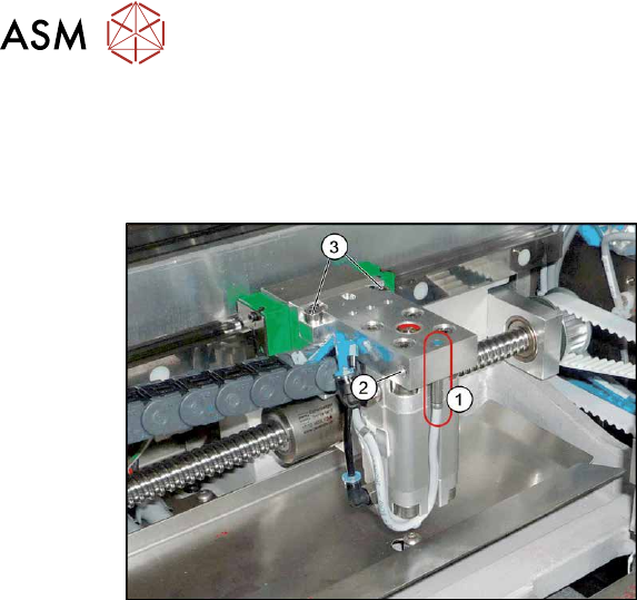
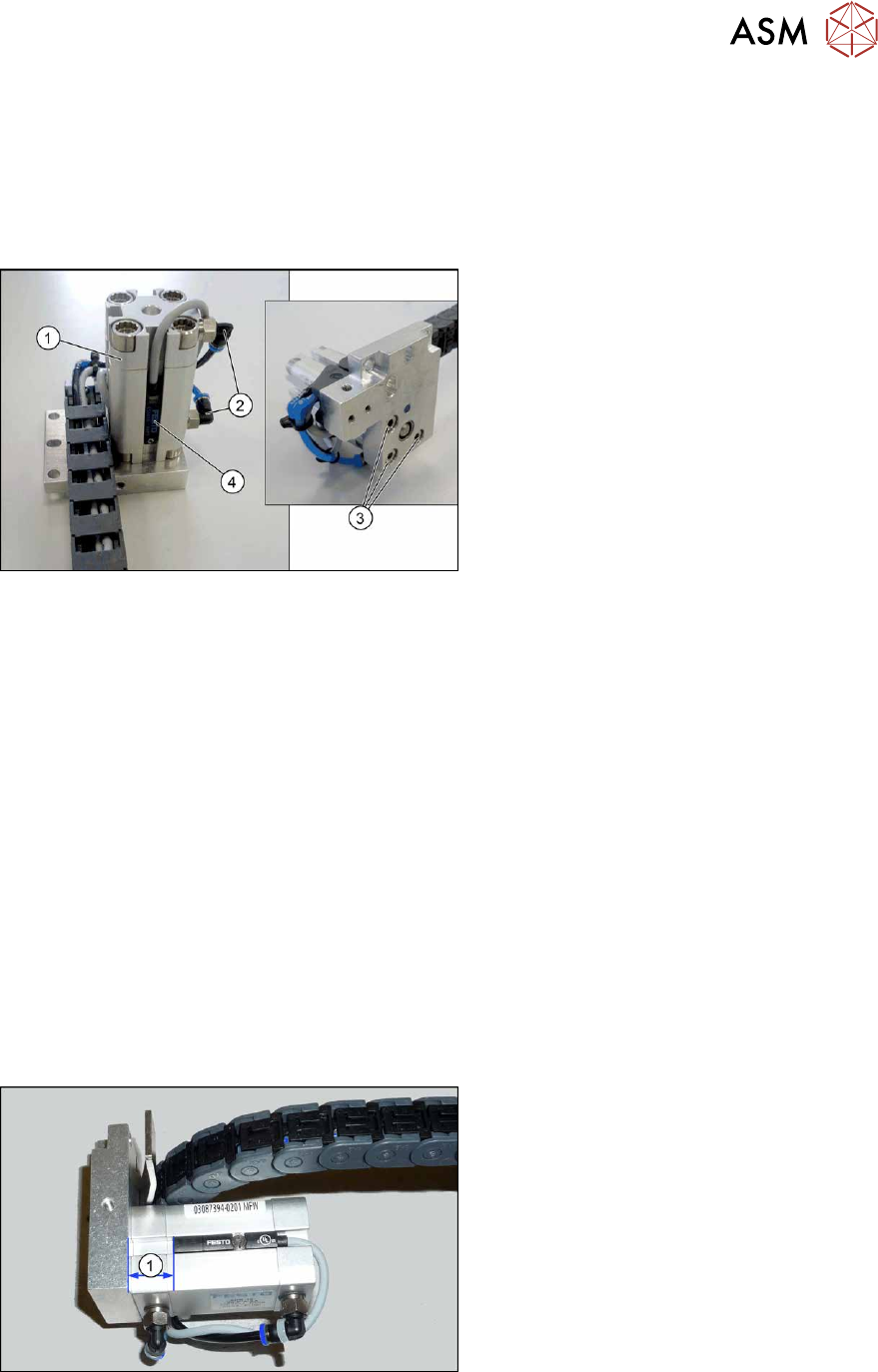
Fig.245: Overview of short-stroke cylinder
1. Short-stroke cylinder
2. Pneumatic connections on short-stroke
cylinder
3. Screws (3x) fastening the short-stroke
cylinder
4. Proximity switch
See also 7.5.1 "Overview of width adjustment" [}181]
Removal
► Remove the cylinder unit. Please read section 7.5.5 "Replacing the cylinder unit (width adjust-
ment) (DC only)" [}185].
► Unplug the pneumatic connections to the short-stroke cylinder. If necessary, mark their posi-
tions to make clear assignment easier later on.
► Remove the screw fastening the proximity switch.
► Remove the three screws holding the short-stroke cylinder.
Installation
Follow the removal instructions in reverse order for installation. Also observe the following instruc-
tions:
► Fasten the proximity switch to the old short-stroke cylinder. Follow the diagram below for this.
► Make sure you have the pneumatic connections in the correct places. These pneumatic con-
nections must be on the side facing away from the trailing cable (see diagram above).
► Make sure that the inserted parallel pin does not protrude above the base unit.
Fig.246: Setting the proximity switch
► Set the distance between the proximity
switch and the upper edge of the short-
stroke cylinder. This depends on the
short-stroke cylinder fitted:
●
Distance 13 mm for "short-stroke cyl-
inder ADN-16-20-P-A-
SA" [03100045‑xx]
●
Distance 10 mm for "short-stroke cyl-
inder ADVU-16-20-P-A-
SA" [00356862‑xx]
7 Conveyor
7.5 Width Adjustment, Clamps and Cylinder Unit
190 Service Manual SIPLACE X-Series S (from Hxxxx) 01/2021
7.5.9 Replacing the valve terminal for cylinders (width adjustment) (DC only)
Parts, equipment and tools
●
Valve terminal 3-fold [03092667-xx]
Overview
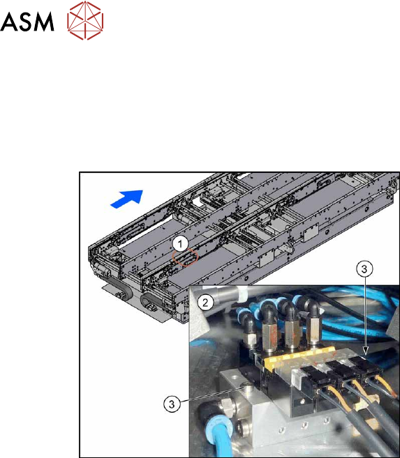
Fig.247: Overview of valve terminal
1. The valve terminal is located in the
center, between location 2 and 3, under
the lifting table plates.
2. Valve terminal
3. Fastening screws (2x) for valve ter-
minal
See also 7.5.1 "Overview of width adjustment" [}181]
Removal
► Use the software to move the conveyor sides into a position which allows you best access. As
an alternative, you can loosen the clamps for the relevant sides in dual conveyors.
7.2 "Loosening the Conveyor Side Clamps" [}162]
► Switch off the machine, disconnect it from the power supply and secure it to prevent
unauthorized reactivation.
1.2 "Preparatory work..." [}16]
► Switch off the compressed air supply
5.2 "Disabling the compressed air supply" [}86]
► Remove the screws fastening the lifting table plate at location 3 and remove the lifting table
plate.
7.3.1 "Replacing the lifting table plate" [}167]
► Remove the two screws fastening the valve terminal.
► Disconnect the valve terminal from the power and pneumatic connections. You might like to
mark their positions to make clear assignment easier later on.
► Take the valve terminal out of the machine.
Installation
Follow the removal instructions in reverse order for installation. Also observe the following instruc-
tions:
► Compare the old and the new valve terminal. You may sometimes have to refit the silencer
and pneumatic connections from the old valve terminal on the new valve terminal.
► Replace any opened cable ties.