00198829-01_SM_X-Series-S_Hxxxx_EN.pdf - 第198页
7 Conveyor 7.5 Width Adjustment, Clamps and Cylinder Unit 198 Service Manual SIPLACE X-Series S (from Hxxxx) 01/2021 7.5.14 Calibrating the adjustment unit NOTICE This chapter is valid for machines with dual conveyor (DC…
7 Conveyor
7.5 Width Adjustment, Clamps and Cylinder Unit
Service Manual SIPLACE X-Series S (from Hxxxx) 01/2021 197
Follow the removal instructions in reverse order for further installation. Also observe the following
instructions:
► Check the input/output functions in the software to make sure that the adjustment units with all
sensors are recognized for all conveyor sides.
► Perform calibration of the fixed conveyor sides on the left and right. If you do not, not all con-
veyor sides will be calibrated (see7.10.3
"Calibrating the Conveyor Rails" [}251]).
This calibration is needed to ensure that the conveyor sides are positioned correctly.
Troubleshooting
NOTICE
Conveyor side was not correctly recognized
► Set the distance between the sensor flag and the adjustment unit so that it is smaller:
0.25 to 0.20mm.
NOTICE
Insufficient clamping power
If the conveyor side clamps are no longer clamping enough, this could be because the con-
veyor side has been moved without the brakes (clamps) being released. In this case, pro-
ceed as follows:
► Remove the clamping unit and check its friction surface. If this is no longer rough,
clean the surface with "universal sanding cleaner". Carefully remove any aluminum
shavings on the friction surface.
► Readjust the clamps as described above and then tighten the screws with 8 Nm.
► If you are unable to set the parallelism of the conveyor sides with the width adjust-
ment, inform your SIPLACE service team.
7.5.13 Replacing the contact plate of the clamping unit (DC only)
Parts, equipment and tools
●
Contact plate clamp unit SXa [03092536-xx]
●
Eraser, if needed
Overview
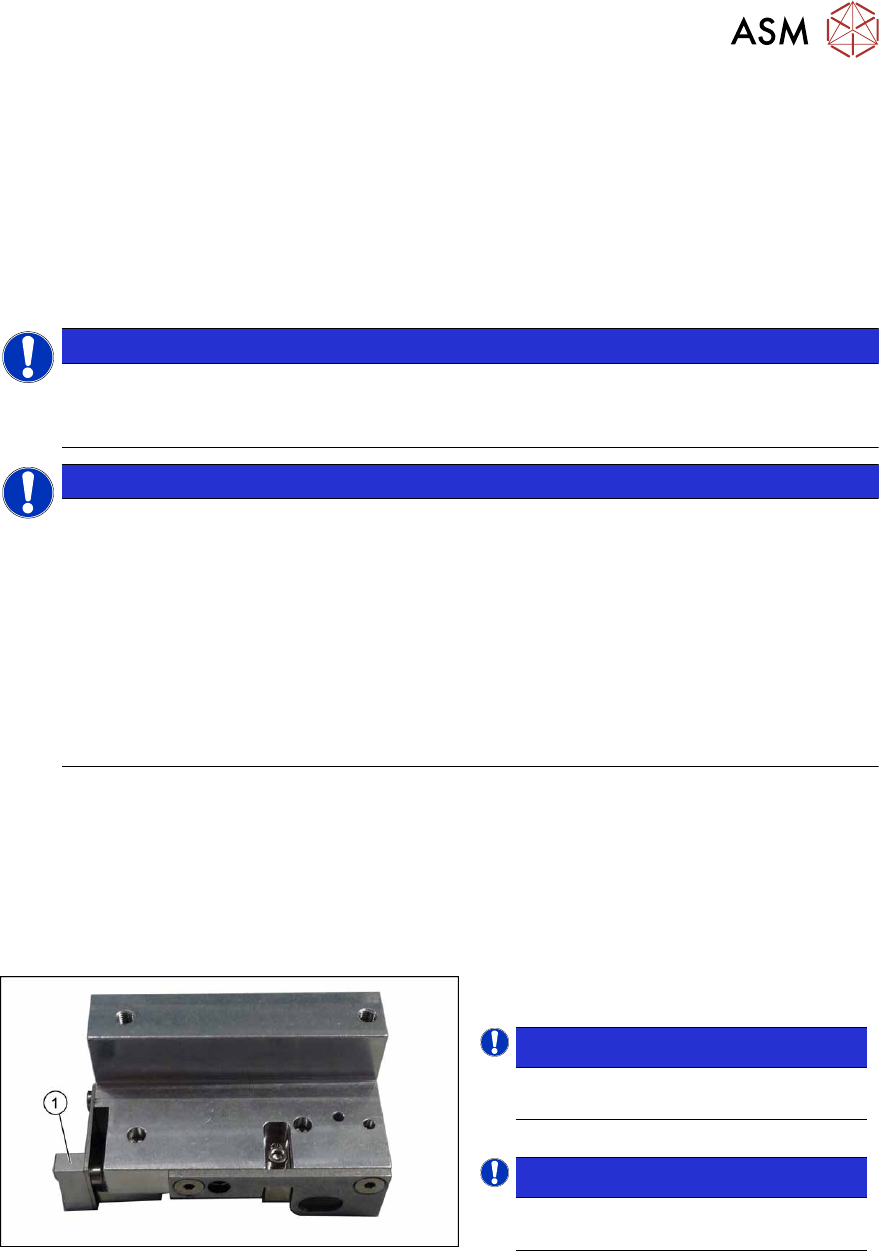
Fig.258: Contact plate
1. Contact plate
NOTICE!
The contact plate is the same through-
out all versions of the clamping unit.
.
NOTICE!
The contact plate can be cleaned us-
ing an eraser.
.
Removal
► Remove the clamping unit. Read the relevant section for this:
7.5.11 "Replacing the Clamping Unit (Version 1) (DC Only)" [}192]
7.5.12 "Replacing the Clamping Unit (Version 2) (DC Only)" [}195]
► Remove the screw fastening the contact plate and then remove the contact plate.
Installation
Follow the removal instructions in reverse order for installation.
7 Conveyor
7.5 Width Adjustment, Clamps and Cylinder Unit
198 Service Manual SIPLACE X-Series S (from Hxxxx) 01/2021
7.5.14 Calibrating the adjustment unit
NOTICE
This chapter is valid for machines with dual conveyor (DC) only.
After completing all work to the width adjustment (adjustment unit, motor or belt of width adjust-
ment), you need to calibrate the adjustment unit before you configure the conveyor sides.
Procedure
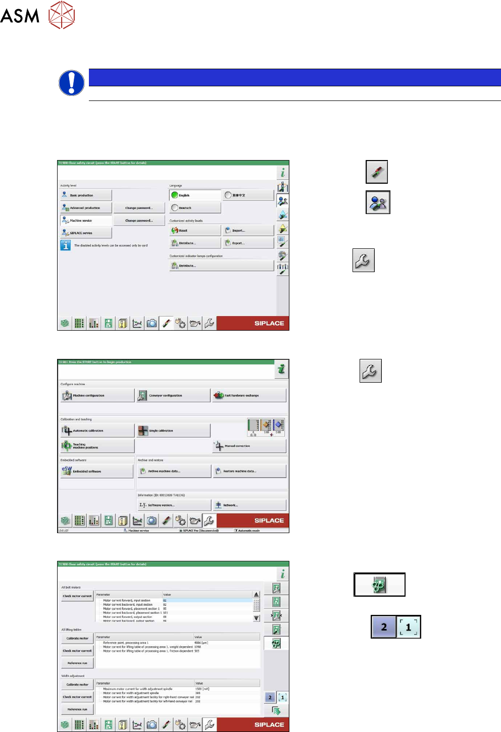
Fig.259: Select operator level
► Select the button.
► Select the button.
► Switch over to the operator level Ma-
chine service.
ð The button will be shown.
Fig.260: Service menu
► Click the button to open the Ser-
vice menu.
► Click on the Conveyor Configuration-
button.
Fig.261: Conveyor menu
► Click on the Initiate conveyor para-
meters button.
► Select the required conveyor track with
the buttons
.
► Go to the section Width adjustment
and select the button Calibrate motor.
7 Conveyor
7.6 Conveyor Belt, Belt Drive and Hexagonal Shaft
Service Manual SIPLACE X-Series S (from Hxxxx) 01/2021 199
7.6 Conveyor Belt, Belt Drive and Hexagonal Shaft
7.6.1 Replacing the Toothed Belt (Conveyor Belt)
Parts, equipment and tools
●
Toothed belt
Select the relevant toothed belt:
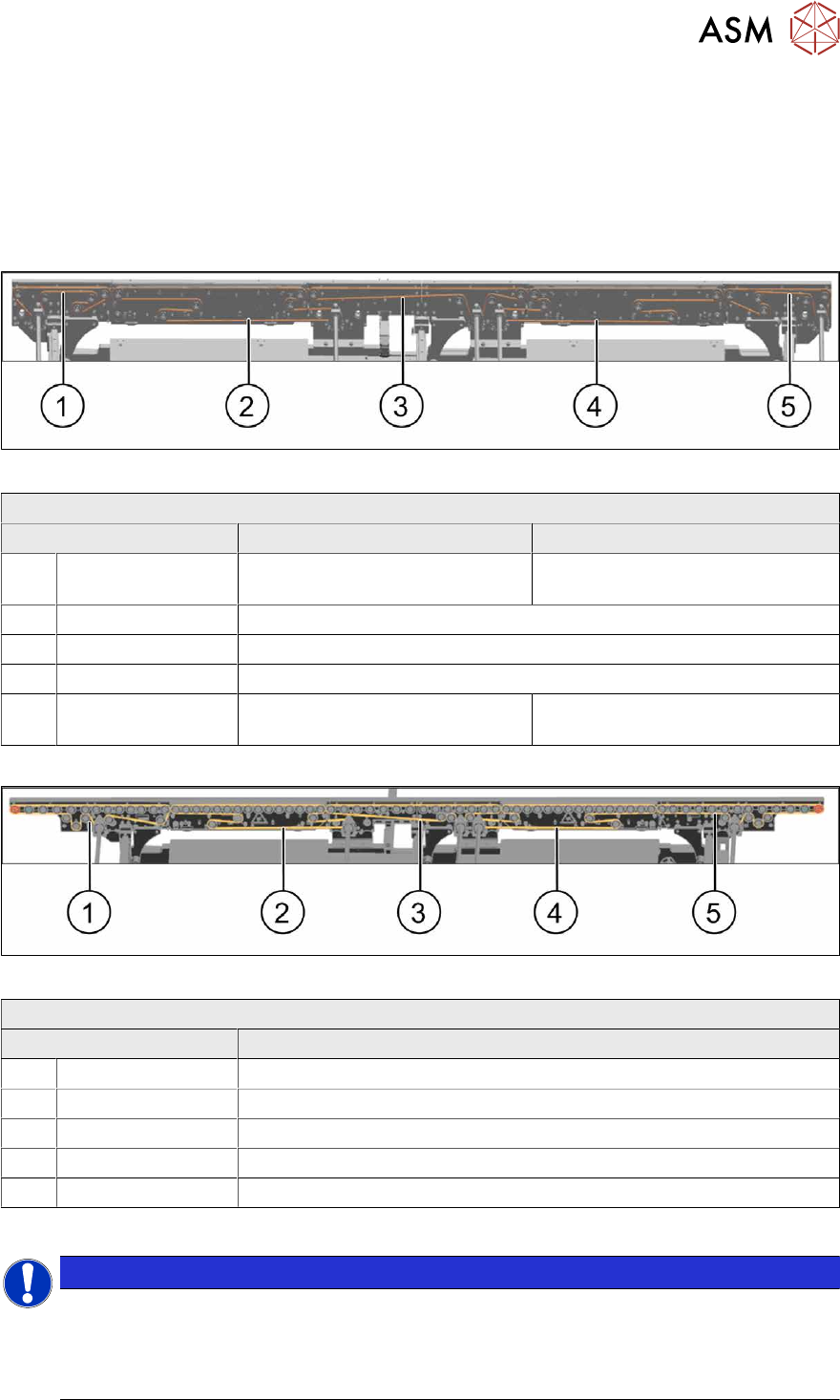
Fig.262: Toothed belt - default conveyor
Toothed belt (conveyor) – single/dual conveyor
Area Standard With I/O extension
1 Input area Synchronous belt L=753mm
[03094116‑xx]
Synchronous belt L=1239mm
[03093312‑xx]
2 PA1 Synchronous belt L=1500 mm [03093146-xx]
3 Center Synchronous belt L=1158 mm [03093314-xx]
4 PA2 Synchronous belt L=1500 mm [03093146-xx]
5 Output area Synchronous belt L=753mm
[03094116‑xx]
Synchronous belt L=1239mm
[03093312‑xx]
Fig.263: Toothed belt – single conveyor, heavy board 8kg
Toothed belt (conveyor) – single conveyor, heavy board 8kg
Area Toothed belt
1 Input area Synchronous belt L=1158 mm / 3 tensile members [03171845Sxx]
2 PA1 Synchronous belt L=1500 mm / 3 tensile members [03171844Sxx]
3 Center Synchronous belt L=1158 mm / 3 tensile members [03171845Sxx]
4 PA2 Synchronous belt L=1500 mm / 3 tensile members [03171844Sxx]
5 Output area Synchronous belt L=1158 mm / 3 tensile members [03171845Sxx]
●
If needed, bearing for hexagonal shaft SXa (plastic bearing) – pack of 10 [03092024-xx]
NOTICE
Checking the toothed belt
► Check the toothed belt regularly for wear (abrasion).
► If the weight of the boards transported is near the upper limit of 8 kg, it is advisable to
replace the toothed belt after one year, as a preventative measure.