00198829-01_SM_X-Series-S_Hxxxx_EN.pdf - 第215页
7 Conveyor 7.7 Clamping Plate, Clamping Rails and Belt Guidance Service Manual SIPLACE X-Series S (from Hxxxx) 01/2021 215 Fig.279: Fiber optic cable transmitter/receiver ► If a fiber optic cable receiver or transmitter…
7 Conveyor
7.7 Clamping Plate, Clamping Rails and Belt Guidance
214 Service Manual SIPLACE X-Series S (from Hxxxx) 01/2021
Side panel (4)
Center PA2
(5)
Placement area 2 (PA 2)
(6)
Output area
DC SC
SIPLACE X4i S
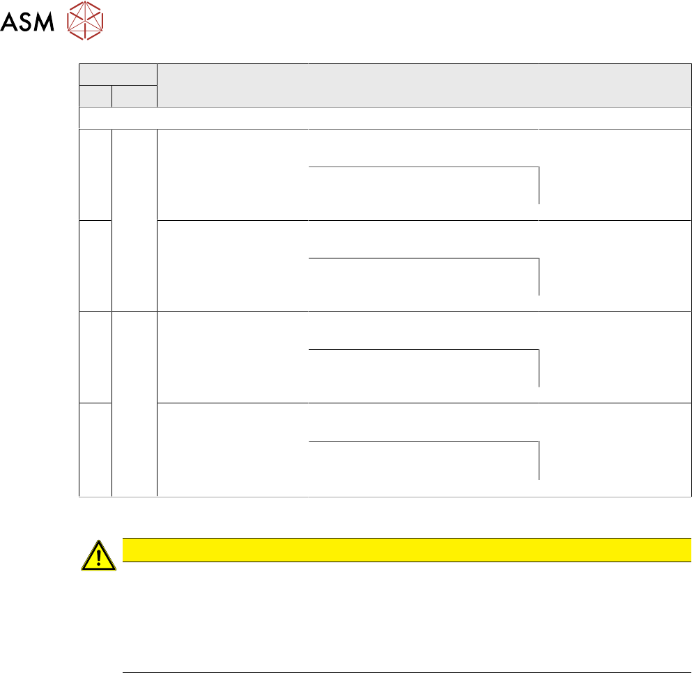
A Fixed
, right
[03093767-xx] Belt
guidance A/C PA2 IC
SX4a
[03094115-xx] Clamping rail A/C
PA2 380 450 assembly SX4a
[03093766-xx] Belt
guidance A/C PA2 OC
SX4a
Thick board: [03100554-xx] clamp-
ing rail TBO A/C PA2 380 450
assembly SX4a
B [03094434-xx] Belt
guidance B/D PA2 IC
SX4a
[03094452-xx] Clamping rail B/D
PA2 450 assembly SX4a
[03094433-xx] Belt
guidance B/D PA2 OC
SX4a
Thick board: [03100563-xx] clamp-
ing rail TBO B/D PA2 450 assembly
SX4a
C Fixed
, left
[03093767-xx] Belt
guidance A/C PA2 IC
SX4a
[03094115-xx] Clamping rail A/C
PA2 380 450 assembly SX4a
[03093766-xx] Belt
guidance A/C PA2 OC
SX4a
Thick board: [03100554-xx] clamp-
ing rail TBO A/C PA2 380 450
assembly SX4a
D [03094434-xx] Belt
guidance B/D PA2 IC
SX4a
[03094452-xx] Clamping rail B/D
PA2 450 assembly SX4a
[03094433-xx] Belt
guidance B/D PA2 OC
SX4a
Thick board: [03100563-xx]
Clamping rail TBO B/D PA2 450
assembly SX4a
Removal
CAUTION
Move the conveyor sides carefully!
The clamping rails and belt guides are a key stabilizing element for the conveyor side,
which is then less stable once they have been removed.
► Move the opened conveyor sides very carefully.
Make sure that the sides are always pushed equally on the left and right.
Also make sure that you do not distort the side panels.
► Use the software to move the conveyor sides into a position which allows you best access. As
an alternative, you can loosen the clamps for the relevant sides in dual conveyors.
7.2 "Loosening the Conveyor Side Clamps" [}162]
► Switch off the machine, disconnect it from the power supply and secure it to prevent
unauthorized reactivation.
1.2 "Preparatory work..." [}16]
► Only in the input, output and intermediate areas: loosen the movable idler pulley for the con-
veyor belt.
7 Conveyor
7.7 Clamping Plate, Clamping Rails and Belt Guidance
Service Manual SIPLACE X-Series S (from Hxxxx) 01/2021 215
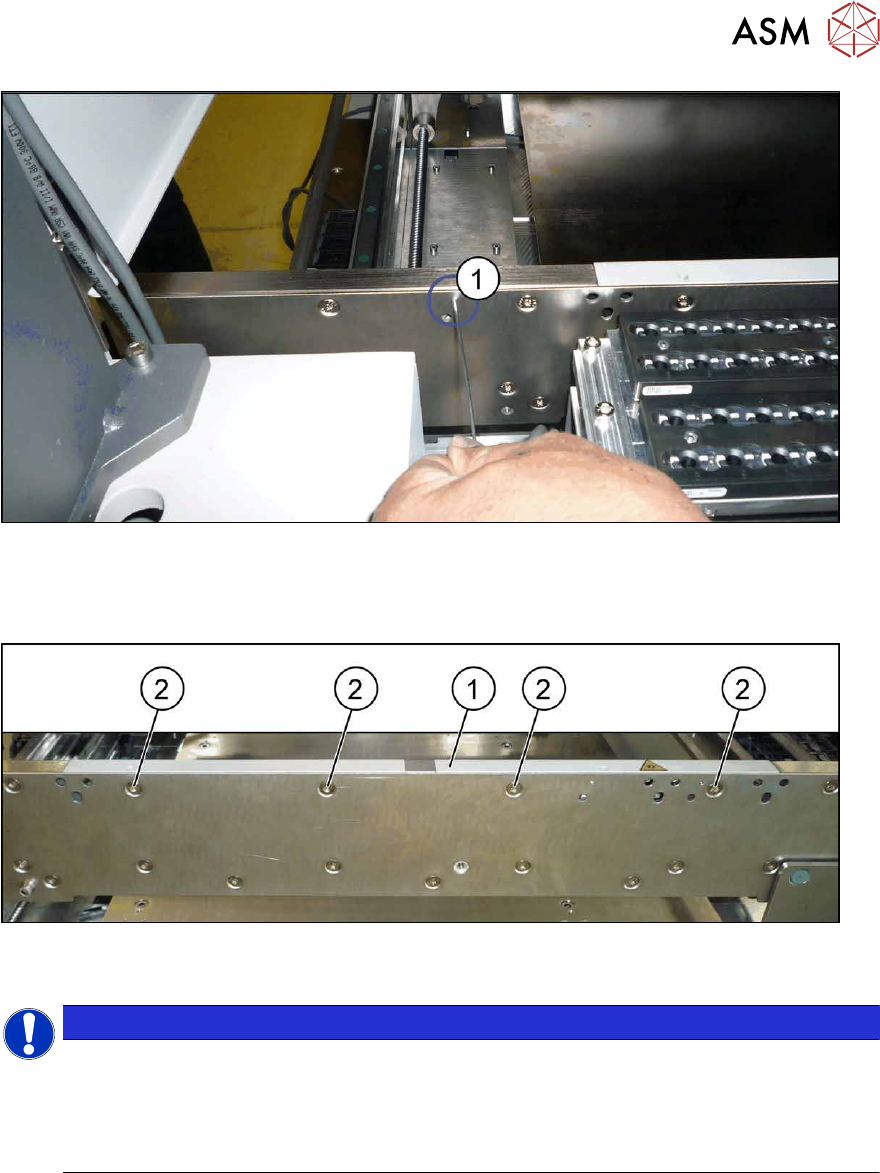
Fig.279: Fiber optic cable transmitter/receiver
► If a fiber optic cable receiver or transmitter is fitted to the rail:
the receiver/transmitter is fixed from the outside to the side wall with a grub screw(1)
. In order
to remove the rail, you need to loosen this grub screw.
Fig.280: Fastening screws (example of clamping rail shown)
► Remove the screws(2) fastening the rail (1) (three or four screws, depending on the position).
NOTICE
Special screws
These are special screws with a length of 14.7 mm.
In some cases, one of the screws may be slightly shorter. In this case, make a note of the
positions, to make clear assignment easier later on. If incorrectly used, you might not be
able to move the clamping plate when it is installed.
► Carefully pull the clamping rail up and off the conveyor side.
► You may need to dismantle the transmitter/receiver fixed to the clamping rail.
Installation
Follow the removal instructions in reverse order for installation. Also observe the following instructions:
► Tighten the rail fastening screws with a torque of 6 Nm. Do not tighten too much. This could
damage the thread or distort the conveyor side.
► Check the setting for the transmitter/receiver and correct if necessary.
7.8.3 "Checking the laser light barrier" [}222]
7.8.4 "Correcting the Laser Light Barrier Setting" [}225]
► Once you have loosened the conveyor belt, set the tension again.
7.6.2 "Setting the belt tension (conveyor belt)" [}200]
7 Conveyor
7.8 Laser light barriers, fiber optic cable and PCB sensors
216 Service Manual SIPLACE X-Series S (from Hxxxx) 01/2021
7.8 Laser light barriers, fiber optic cable and PCB sensors
7.8.1 Replacing the Laser Light Barrier for the Transmitter/Receiver
Parts, equipment and tools
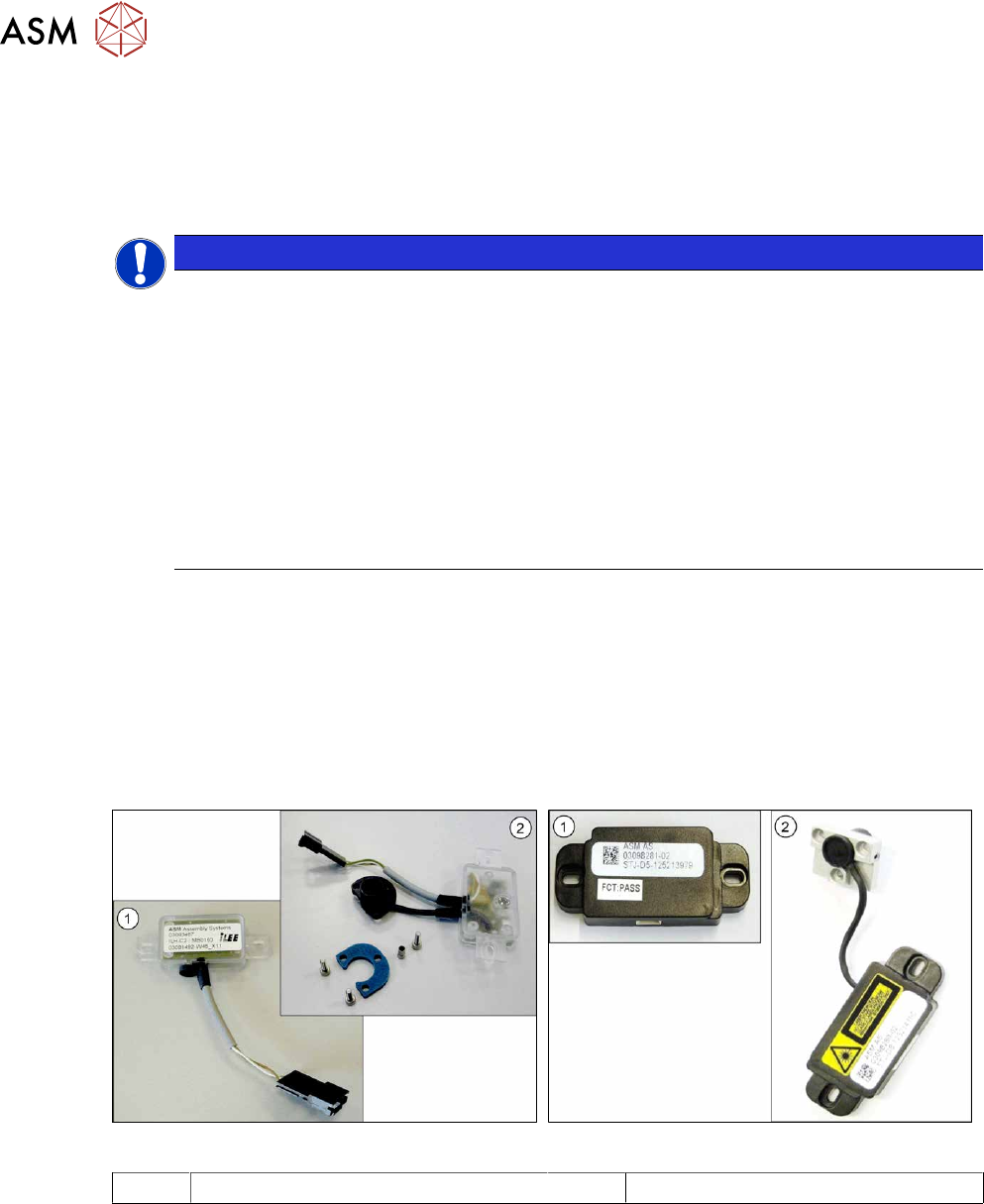
NOTICE
Old and new version of transmitter and receiver
There are old and new versions of the transmitter and receiver modules.
Old: [03092578-xx], [03091492-xx]
New: [03109439‑xx] (contains: 03098280-xx, 03098281-xx)
► The old version can be replaced with the new one.
► The transmitter and receiver of the new version are coordinated with one an-
other and must always be replaced together. It is not possible to just replace the
transmitter or receiver alone.
► In the old version, the connection cable is fixed to the module.
In the new version, the connection cable has a plug at each end. In this case, the con-
nection cable needs to be connected to the module before it is fitted.
●
Light barrier transmitter and receiver SX1V2 / X‑SeriesS [03109439‑xx] (replaces:
03092578‑xx, 03091492‑xx)
●
Flashlight, if needed
●
Magnet lifter, if needed
●
Tweezers, if needed
●
If needed, semi-transparent paper or plastic (for better recognition of the laser beam)
Overview
Fig.281: Receiver and transmitter (old version)
Fig.282: Receiver and transmitter (new version)
1 Receiver 2 Transmitter