00198829-01_SM_X-Series-S_Hxxxx_EN.pdf - 第223页
7 Conveyor 7.8 Laser light barriers, fiber optic cable and PCB sensors Service Manual SIPLACE X-Series S (from Hxxxx) 01/2021 223 Fig.293: Safety mode ► Enable the button Safety mode (re- duced speed) . Fig.294: Check …
7 Conveyor
7.8 Laser light barriers, fiber optic cable and PCB sensors
222 Service Manual SIPLACE X-Series S (from Hxxxx) 01/2021
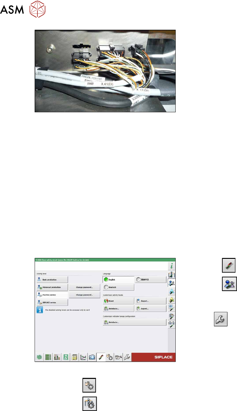
Fig.291: Connections (here output conveyor location 3)
► Disconnect the cable. You may want to
mark the position, to make clear as-
signment easier later on.
Installation
Follow the removal instructions in reverse order for installation. Also observe the following instruc-
tions:
► Leave enough room at the cable for easy removal of the transmitter/receiver from the side
wall. Make sure that the connector is not directly under the housing, otherwise you might have
problems inserting the module.
► Replace any open cable ties.
Make sure that the cable ties and the heads of the cable ties do not rub against any parts
when you do this.
► Check the setting for the transmitter/receiver and correct if necessary.
► Teach the PCB sensors.
7.8.3 Checking the laser light barrier
Whenever the laser light barrier is dismantled, it then needs to be checked and manually set again,
if necessary. Check the setting as follows:
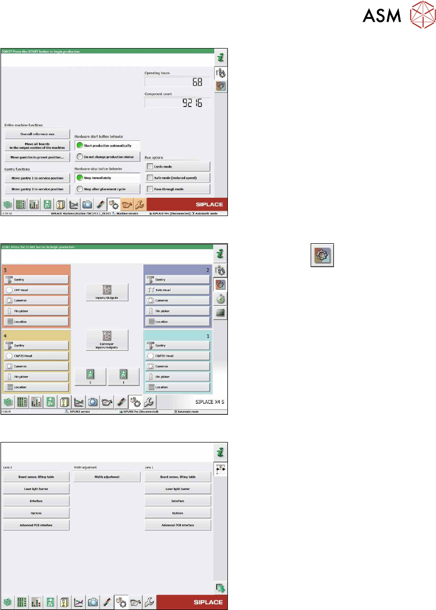
Fig.292: Select operator level
► Select the button.
► Select the button.
► Switch over to the operator level Ma-
chine service.
ð The button will be shown.
► Click on the button, to switch over to the menu Check sensors and functions.
► Click on the button.
7 Conveyor
7.8 Laser light barriers, fiber optic cable and PCB sensors
Service Manual SIPLACE X-Series S (from Hxxxx) 01/2021 223
Fig.293: Safety mode
► Enable the button Safety mode (re-
duced speed).
Fig.294: Check sensors and functions
► Click on the button.
► Click on the Conveyor inputs/outputs
button.
Fig.295: Inputs/outputs
► Click on the button Sensors.
7 Conveyor
7.8 Laser light barriers, fiber optic cable and PCB sensors
224 Service Manual SIPLACE X-Series S (from Hxxxx) 01/2021
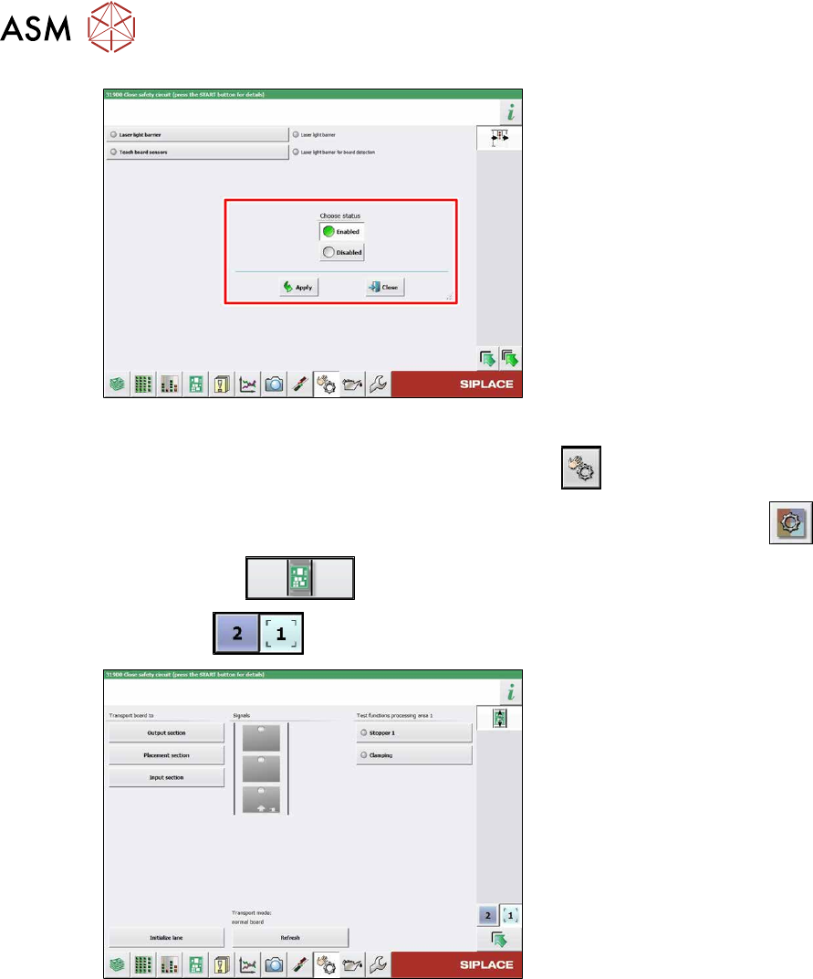
Fig.296: Sensors
► Enable the Laser light barrier button.
► Click on the button Check sensors and functions .
► Click on the button Check sensors and functions of specific components .
► Click on the button.
► Use the button to select the required conveyor track.
Fig.297: Checking function of the laser light
► Check the function of the laser light
barrier. To do this, move a board
through the conveyor.
► Correct the laser light barrier setting, if
necessary (see below).