00198829-01_SM_X-Series-S_Hxxxx_EN.pdf - 第225页
7 Conveyor 7.8 Laser light barriers, fiber optic cable and PCB sensors Service Manual SIPLACE X-Series S (from Hxxxx) 01/2021 225 7.8.4 Correcting the Laser Light Barrier Setting DANGER Laser class 2 The laser light barr…
7 Conveyor
7.8 Laser light barriers, fiber optic cable and PCB sensors
224 Service Manual SIPLACE X-Series S (from Hxxxx) 01/2021
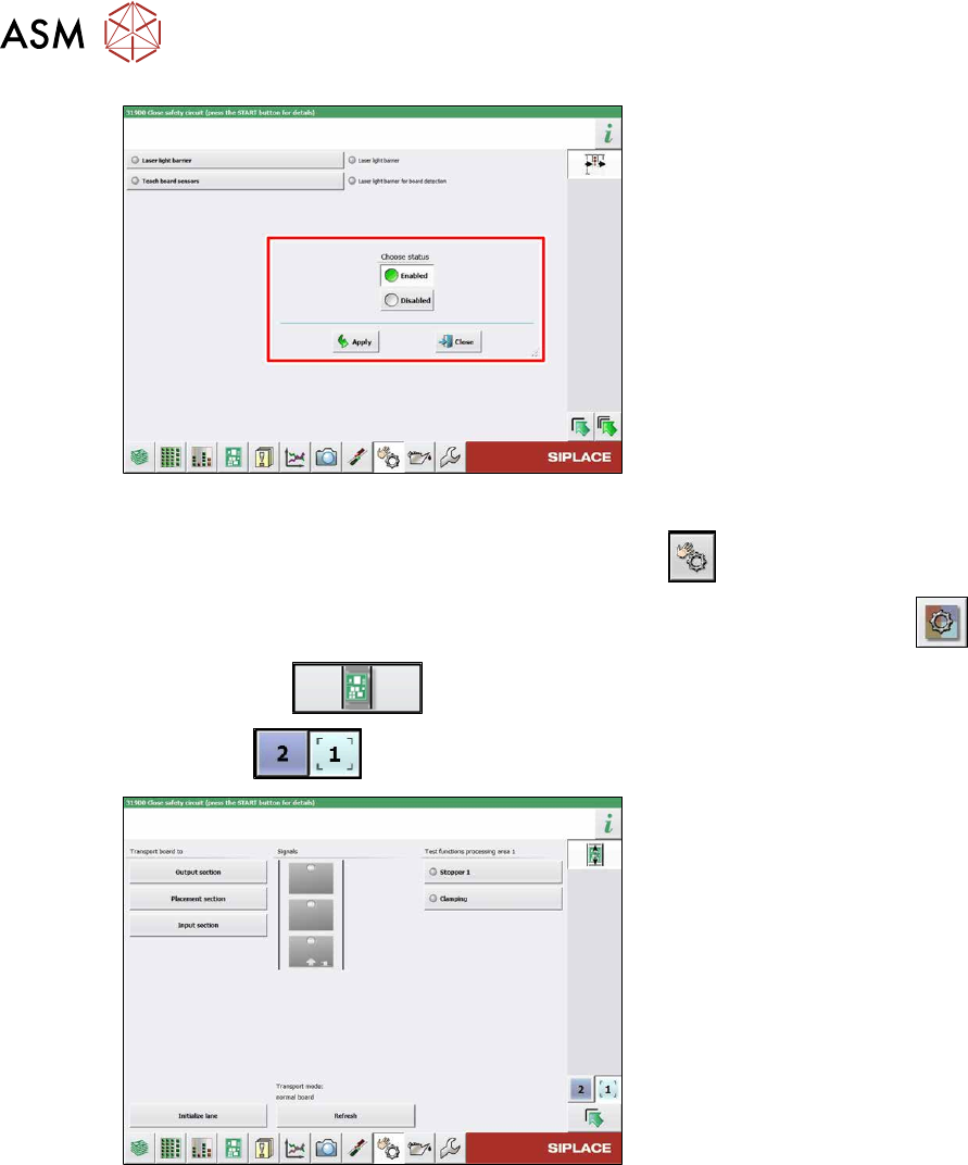
Fig.296: Sensors
► Enable the Laser light barrier button.
► Click on the button Check sensors and functions .
► Click on the button Check sensors and functions of specific components .
► Click on the button.
► Use the button to select the required conveyor track.
Fig.297: Checking function of the laser light
► Check the function of the laser light
barrier. To do this, move a board
through the conveyor.
► Correct the laser light barrier setting, if
necessary (see below).
7 Conveyor
7.8 Laser light barriers, fiber optic cable and PCB sensors
Service Manual SIPLACE X-Series S (from Hxxxx) 01/2021 225
7.8.4 Correcting the Laser Light Barrier Setting
DANGER
Laser class 2
The laser light barrier transmitter emits class 2 laser beams. You therefore do not require
additional protective measures!
► However, you should never look into the laser beam!
► Adjust the laser beam only from the rear side of the laser!
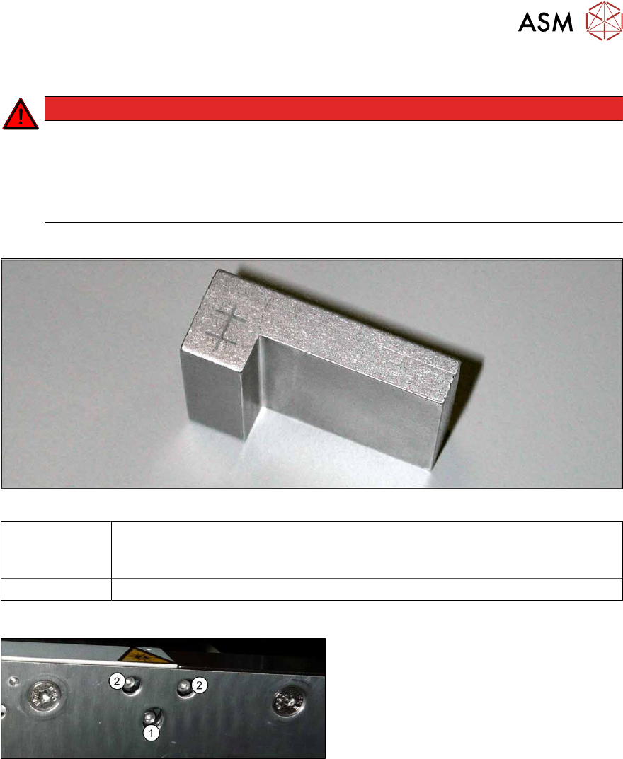
Equipment and tools
Fig.298: Setting gauge
00369205-xx Adjusting gauge "Adjustment of laser, PCB conveyor"
Semi-transparent paper or plastic laminate can be used as an alternative, for
better recognition of the laser beam.
00353832-xx Allen key set
Overview
Fig.299: Laser transmitter
The fastening screw(1) is tightened by
hand.
The adjustment screws(2) might not be fully
tightened, depending on the setting.
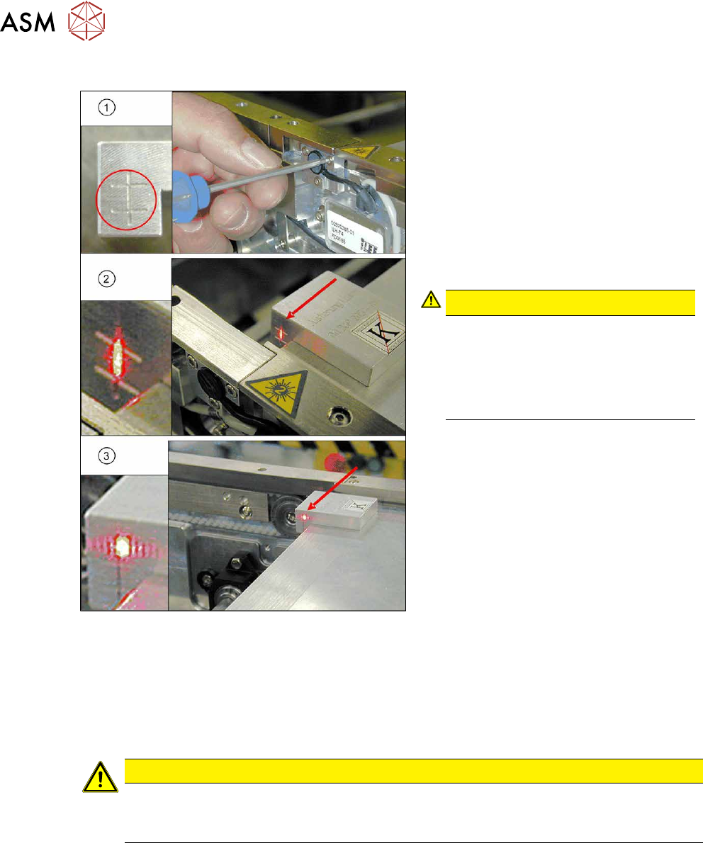
Preparation
► Set the conveyor to the maximum width, to maximize any potential deviation of the laser
beam.
► Select Enable safety mode in software.
► Activate the relevant laser diode using the input/output functions in the station software.
7 Conveyor
7.8 Laser light barriers, fiber optic cable and PCB sensors
226 Service Manual SIPLACE X-Series S (from Hxxxx) 01/2021
Setting with the adjusting gauge
Fig.300: Focusing the laser beam (example of X-Series
shown)
1. Setting the laser light barrier
2. Minimum width
3. Maximum width
► Check the path of the laser beam at
maximum width (3)
with the help of the
adjusting gauge.
► With the help of the three setting
screws, adjust the laser beam to the
center of the gauge cross (1)
.
CAUTION!
Screws on the laser transmitter
Hand-tighten the lower screw. The top
two screws are used to set the laser
beam. These may not be fully
tightened. Otherwise the laser trans-
mitter could be damaged.
.
► Check the setting at minimum width(2).
► Check the PCB reference corner and
reteach, if necessary.
Setting without adjusting gauge
► Check the path of the laser beam with the help of the semi-transparent paper or the laminate.
► Use the top two screws to set the laser beam so that it is correctly aligned with the laser recei-
ver.
CAUTION
Screws on the laser transmitter
► Hand-tighten the lower screw. The top two screws are used to set the laser beam.
These may not be fully tightened. Otherwise the laser transmitter could be damaged.
► Now position the conveyor to minimum width and check the setting.
► Check the PCB reference corner and reteach, if necessary.