00198829-01_SM_X-Series-S_Hxxxx_EN.pdf - 第235页
7 Conveyor 7.8 Laser light barriers, fiber optic cable and PCB sensors Service Manual SIPLACE X-Series S (from Hxxxx) 01/2021 235 7.8.8 Setting the fiber optic sensor The brightness of the sensors changes according to th…
7 Conveyor
7.8 Laser light barriers, fiber optic cable and PCB sensors
234 Service Manual SIPLACE X-Series S (from Hxxxx) 01/2021
Removal
CAUTION
Do not bend the fiber optic cable
► Make sure you do not bend the fiber optic cable. These will otherwise become cloudy
and no longer transmit the signal properly.
► Use the software to move the conveyor sides into a position which allows you best access. As
an alternative, you can loosen the clamps for the relevant sides in dual conveyors.
7.2 "Loosening the Conveyor Side Clamps" [}162]
► Switch off the machine, disconnect it from the power supply and secure it to prevent
unauthorized reactivation.
1.2 "Preparatory work..." [}16]
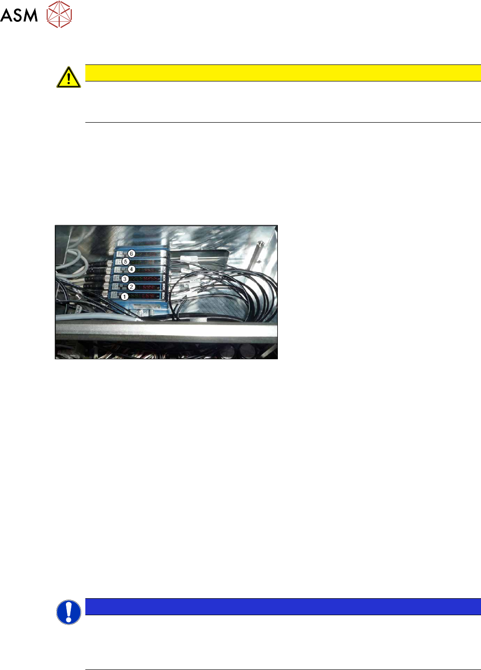
► Dismantle the cover on the fiber optic sensors.
Fig.310: Fiber optic cable sensors
The individual sensors are connected to one
another via a small terminal strip. Dismantle
the sensors one after one, beginning with
(1)
, until you have reached the sensor to be
replaced. Perform the following tasks at
each sensor:
► Open the cover.
► Open the lock on the fiber optic cables and then unplug the fiber optic cables. You may want
to mark their positions, to make clear assignment easier later on.
► Disconnect from the power supply. You may want to mark the position of this connection to
make clear assignment easier later on.
► Pull the sensor slightly away from the other sensors. Now you can pull the sensor up and off
the strip.
► Repeat these steps if needed for any other sensors.
Installation
Installation is performed by following the above instructions in the reverse order. Also observe the
following instructions:
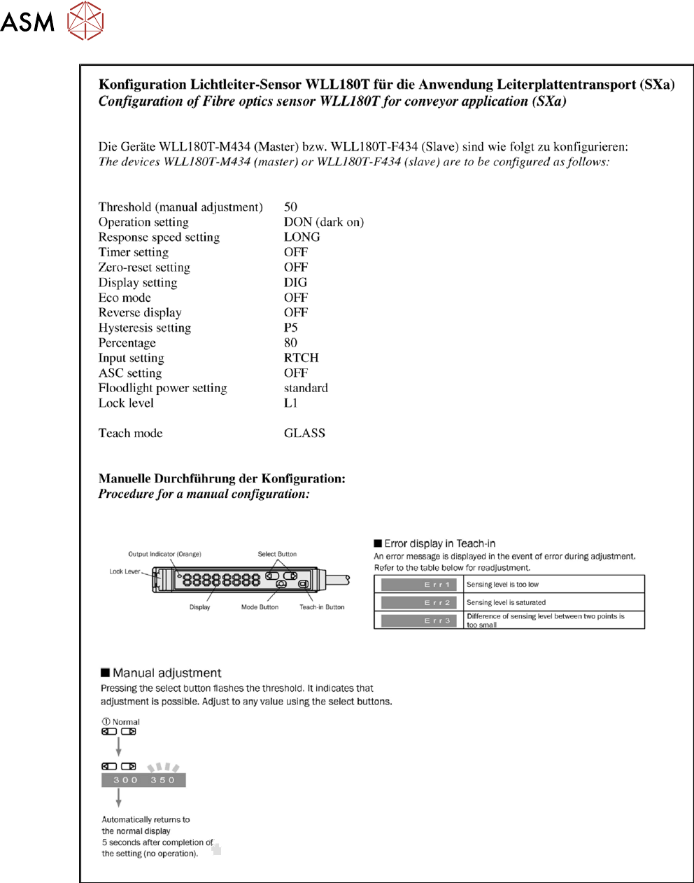
► Check the setting on the fiber optic sensor and correct if necessary. (See 7.8.8 "Setting the
fiber optic sensor" [}235])
New sensors are preset.
► Remove the plastic cover for the sensor on the side press-fit connections, if needed.
NOTICE
End stops
The fiber optic cable sensors are held at both ends by end stops. If these end stops are
missing or are defective, this can lead to loose connections.
► Replace the end stops when needed.
► Teach the PCB sensors.
7 Conveyor
7.8 Laser light barriers, fiber optic cable and PCB sensors
Service Manual SIPLACE X-Series S (from Hxxxx) 01/2021 235
7.8.8 Setting the fiber optic sensor
The brightness of the sensors changes according to the positions of the conveyor sides. For this
reason, the sensors are automatically recalibrated after each automatic adjustment of the conveyor
sides.
If the conveyor sides are manually adjusted, there will be no automatic calibration. In this case cali-
bration needs to be manually triggered in the Service menu. Without this calibration the station soft-
ware will show boards which are not physically present.
You can check the correct calibration on the sensor modules.
●
Red display: current signal strength of receiver
●
Green display: reference value of receiver
A board is recognized if the value in the red display is smaller than the value in the green display.
Without a board, the value of the green display must be 10 to 20% smaller than the value of the
red display.
During calibration, the reference value (green display) is automatically set to a lower value than the
current signal strength (red display). It is assumed that there is no board in the sensor range at this
moment.
The absolute sensor value is not significant. This can vary between sensor modules.
NOTICE
No board in conveyor
When calibrating the light barriers make sure that there is no board in the conveyor.
7 Conveyor
7.8 Laser light barriers, fiber optic cable and PCB sensors
236 Service Manual SIPLACE X-Series S (from Hxxxx) 01/2021
Fig.311: Setting the fiber optic sensor - 1