00198829-01_SM_X-Series-S_Hxxxx_EN.pdf - 第242页
7 Conveyor 7.9 Boards 242 Service Manual SIPLACE X-Series S (from Hxxxx) 01/2021 Fig.320: Spacer bolts ► Remove the four spacer bolts (1) . ► Remove the conveyor control together with the mounting plate from the machin…
7 Conveyor
7.9 Boards
Service Manual SIPLACE X-Series S (from Hxxxx) 01/2021 241
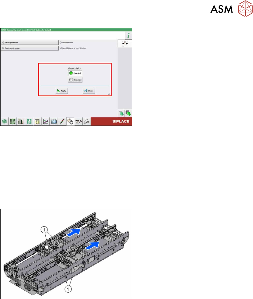
Fig.318: Teaching the sensors
► Select Laser light barrier at conveyor
track 1.
Enable Teach board sensors
and
press the Start button on the machine.
Disable this function again afterwards.
► Repeat this step for all tracks.
7.9 Boards
7.9.1 Replacing the conveyor control TSP420
Parts, equipment and tools
●
Conveyor control TSP420 assembly [03087642-xx]
Overview
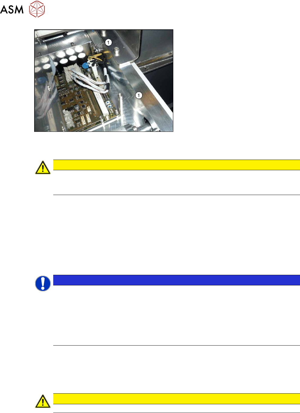
Fig.319: Overview of conveyor controls
The conveyor control units are located under
the covers (1)
in the intermediate conveyor.
Two TSP420s are fitted on single convey-
ors; four are fitted on dual conveyors.
Removal
► Use the software to move the conveyor sides into a position which allows you best access. As
an alternative, you can loosen the clamps for the relevant sides in dual conveyors.
7.2 "Loosening the Conveyor Side Clamps" [}162]
► Switch off the machine, disconnect it from the power supply and secure it to prevent
unauthorized reactivation.
1.2 "Preparatory work..." [}16]
► Remove the screws fastening the lifting table plate and remove the lifting table plate.
7.3.1 "Replacing the lifting table plate" [}167]
► Remove the screws fastening the cover plate above the conveyor control and remove the
cover plate.
► Unplug all electrical connections to the conveyor control. Mark their positions, to make clear
assignment easier later on.
7.9.1.1 "Conveyor control TSP420" [}242]
7 Conveyor
7.9 Boards
242 Service Manual SIPLACE X-Series S (from Hxxxx) 01/2021
Fig.320: Spacer bolts
► Remove the four spacer bolts(1).
► Remove the conveyor control together with the mounting plate from the machine.
CAUTION
Do not remove the conveyor control from the mounting plate
The conveyor control may not be removed from the mounting plate because the mounting
plate serves as a cooling element for the conveyor control.
Installation
Follow the removal instructions in reverse order for installation. Also observe the following instruc-
tions:
► Check the jumper setting: jumper 2 for the internal CAN bus must be set to 2-3 for both
TSP420 in the dual conveyor (CAN terminal resistance for internal conveyor CAN bus).
► Check the firmware and perform a download, if needed. (see 10.1 "eSW Download (SW
70x)" [}379]).
Troubleshooting
NOTICE
Internal CAN bus error on the conveyor control for dual conveyor
In the dual conveyor, the multiple use of the conveyor control can lead to incorrect jumper
settings and internal CAN bus errors.
ü FM35376: Transmission error for internal CAN bus
ü FM35345: Communication problem with internal CAN bus in placement area 2
► Read the technical information "Internal CAN bus error on the conveyor control for
dual conveyors" [DE: TI2014-07D08] [EN: TI2014-07E08].
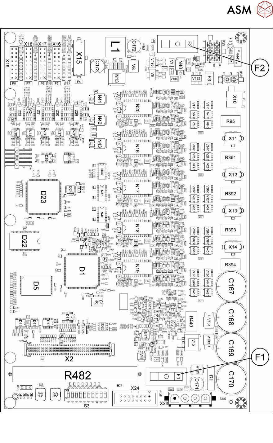
7.9.1.1 Conveyor control TSP420
The conveyor control "TSP420 assembly" [03087642-xx] comprises the following components:
●
Main board: TSP420-M [ 03087640-xx ]
●
I/O board: TSP420-IO [ 03087641-xx ]
CAUTION
These two boards may not be separated!
Depending on the conveyor version, either two (SC) or four (DC) TSP420 are fitted in X-Series S
machines.
7 Conveyor
7.9 Boards
Service Manual SIPLACE X-Series S (from Hxxxx) 01/2021 243
Fig.321: 03087640-02
Spare fuses:
●
F1: Fuse T5A 1500A 5x20mm SPT series (0001.2511 Schurter)
●
F2: Fuse T2A 5x20mm (0034.3120 Schurter / 0239 002 XP Littelfuse)