00198829-01_SM_X-Series-S_Hxxxx_EN.pdf - 第26页
2 Basic Machine 2.3 Guide Rollers on the Covers 26 Service Manual SIPLACE X-Series S (from Hxxxx) 01/2021 Removal/installation ► To make the work easier: Dismantle the bottom stop. Fig.11: Threaded pin ► Loosen the thre…
2 Basic Machine
2.3 Guide Rollers on the Covers
Service Manual SIPLACE X-Series S (from Hxxxx) 01/2021 25
Installation
Follow the removal instructions in reverse order for installation. Also observe the following instruc-
tions:
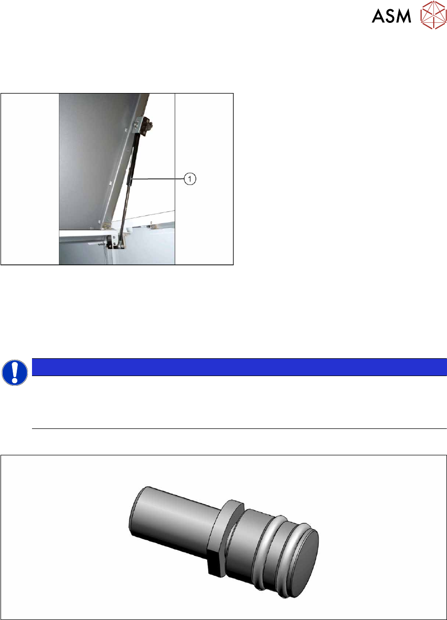
Fig.9: Gas pressure shock absorber
► Observe the correct installation direc-
tion for the gas pressure shock ab-
sorber(1)
.
► You may have to compress the gas
pressure shock absorber slightly when
installing it.
► Fix the gas pressure shock absorber
into place with the circlips.
► Check the cover for ease of movement and adjust if required.
2.4 "Setting the Covers" [}27]
2.3 Guide Rollers on the Covers
NOTICE
Example shown as diagram
The following sections are described using the example of a SIPLACE SX1 machine. The
procedure is the same for other machine types. Any relevant differences will be mentioned
explicitly.
Parts
Fig.10: Guide roller [03078561-xx]
●
Per cover:
– 2x roller assy – 1 unit [03078561-xx]
– 2x DIN EN ISO 4028 M8x16-A2-21H – pack of 10 [03027433‑xx] (replaces[00304354‑xx])
or
2x DIN EN ISO4026-M8x16-A2-21H - pack of 10 [03025582-xx]
Equipment and tools
●
Fork wrench, size 10
●
Allen key
2 Basic Machine
2.3 Guide Rollers on the Covers
26 Service Manual SIPLACE X-Series S (from Hxxxx) 01/2021
Removal/installation
► To make the work easier:
Dismantle the bottom stop.
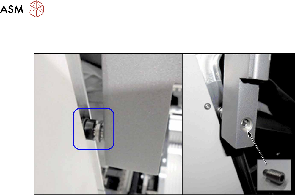
Fig.11: Threaded pin
► Loosen the threaded pin and twist the roller out.
► Insert the new roller.
► From the inside, screw on a threaded pin as lock and tighten it.
Checks
► Between the roller and the guidance there must be at least 75% coverage along the entire
length of the guide rails.
► Check whether the cover can be easily moved along the whole area. Adjust the cover if ne-
cessary.
2.4 "Setting the Covers" [}27]
2 Basic Machine
2.4 Setting the Covers
Service Manual SIPLACE X-Series S (from Hxxxx) 01/2021 27
2.4 Setting the Covers
2.4.1 Overview
Fig.12: Overview of Settings
1. Setting the cover switch
See 2.4.2
"Setting the Cover
Switch" [}27]
2. Setting the cover switch centering
See 2.4.3
"Setting the Cover Switch
Centering Device" [}28]
3. Setting the actuator
See 2.4.4
"Setting the Actuator" [}29]
4. Setting the bottom stop
See 2.4.5
"Setting the Bottom
Stop" [}29]
5. Setting the rollers
See 2.4.6
"Setting the Cover
Rollers" [}30]
2.4.2 Setting the Cover Switch
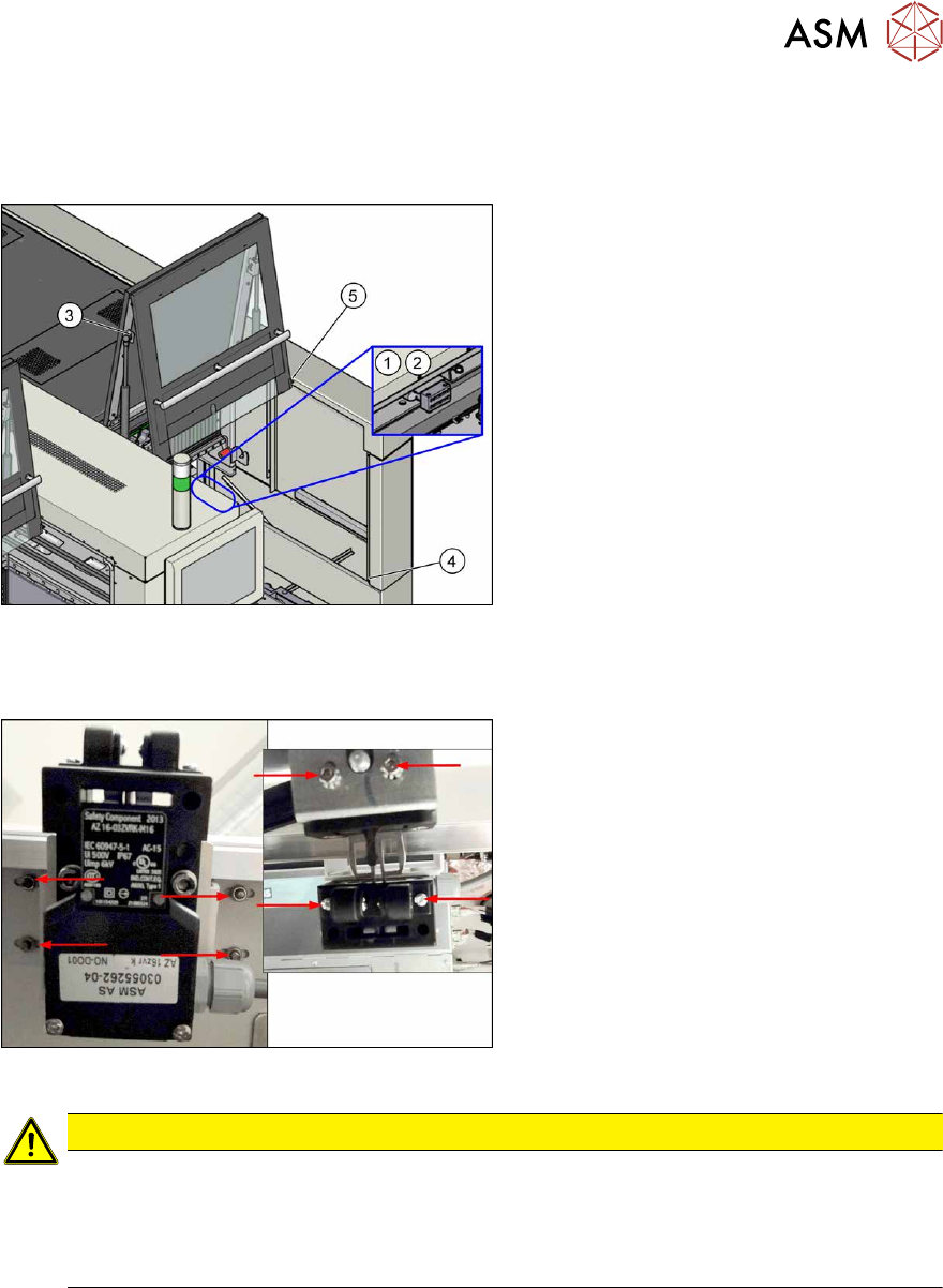
Fig.13: Cover switch (example of SIPLACE SX2 shown)
Cover switch [03055262-xx]
► Loosen the screws fastening the cover
switch, the centering device and the ac-
tuator, so that the assemblies can be
easily moved.
CAUTION
Screws on actuator
With enforcement of the Machinery Directive DIN EN 1088 (2009), the following has been
executed to avoid misuse (e.g. putting the safety features out of action): the actuator and
machine protective switch screws have been replaced by Torx screws with pins. The relev-
ant set of tools may only be used for performing repair work.