00198829-01_SM_X-Series-S_Hxxxx_EN.pdf - 第262页
8 Head exchange 8.5 Replacing the SIPLACE C&P20P/M2 262 Service Manual SIPLACE X-Series S (from Hxxxx) 01/2021 Overview Fig.346: SIPLACE C&P20P 1. Holding circuit connection 2. Intermediate distributor board (…
8 Head exchange
8.5 Replacing the SIPLACE C&P20P/M2
Service Manual SIPLACE X-Series S (from Hxxxx) 01/2021 261
Parts, equipment and tools
●
SIPLACE C&P20P [03091157‑xx] (without camera)
●
SIPLACE C&P20M2 [03125907Sxx] (without camera)
NOTICE
Vacuum pump/compressed air operation
As a spare part, the head is prepared for vacuum pump operation and is fitted with the
"Aperture ring assembly C&P20 P" [03116883‑xx].
► The SIPLACE C&P20P/M2 must be converted with the conversion kit "Compressed
air C&P20x" [03106765‑xx] or with the "Holding circuit assembly
C&P20" [03005123Sxx] for operation in compressed air mode.
●
Torx screwdriver ESD 1.0-5.0 Nm [03078400-xx]
●
Bit holder for TorqueVario screwdriver [03078706-xx]
●
Extension/straight TX20 [03073256-xx]
●
Torx offset screwdriver TX8 [03080081-xx]
Fig.345: Component sensor protective cap
[03092400‑xx]
●
Component sensor protective cap
[03092400‑xx]
●
Calibration tool version SST23 [03034148-
xx]
●
Calibration tool SST48/49 [03157023-xx]
For additional work to the placement head:
●
Head mount [03056231‑xx]
●
Service manual "SIPLACE C&P20P" [DE:00197489‑xx] [EN:00197490‑xx]
●
Job Card "Preventive Maintenance C&P20P" [DE:00197529‑xx] [EN:00197528‑xx] (other
languages available)
If needed, for vacuum pump operation:
●
Assembly instructions "Option Vacuum Pump SIPLACE X-Series S from Hxxxx " [DEEN:
00198599‑xx]
8 Head exchange
8.5 Replacing the SIPLACE C&P20P/M2
262 Service Manual SIPLACE X-Series S (from Hxxxx) 01/2021
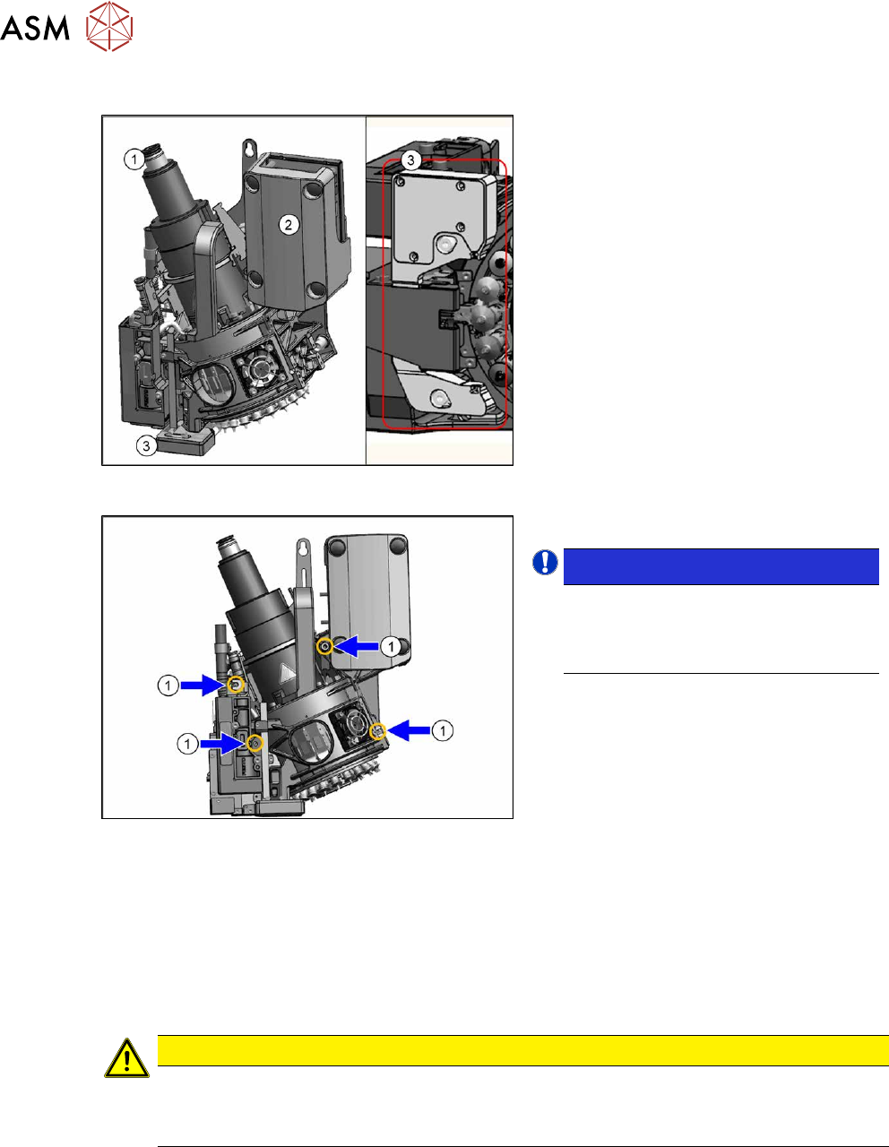
Overview
Fig.346: SIPLACE C&P20P
1. Holding circuit connection
2. Intermediate distributor board (behind
the cover)
3. Component sensor
Fig.347: Fastening screws
1. Four fastening screws (yellow marks)
NOTICE!
The length of the exhaust air hose "Sil-
icon hose Di8 Da12 electrically con-
ductive 1m" [03006727Sxx] on the
SIPLACE C&P20P/M2 is 355mm.
.
Removal
► Switch off the machine, disconnect it from the power supply and secure it to prevent
unauthorized reactivation.
1.2 "Preparatory work..." [}16]
► Switch off the compressed air supply
5.2 "Disabling the compressed air supply" [}86]
CAUTION
Take great care when dismantling the placement head!
The component sensor prisms, underneath the placement head, could be damaged.
► Never place the placement head down on the component sensor.
► Fit the protective cap onto the component sensor for the placement head.
8 Head exchange
8.5 Replacing the SIPLACE C&P20P/M2
Service Manual SIPLACE X-Series S (from Hxxxx) 01/2021 263
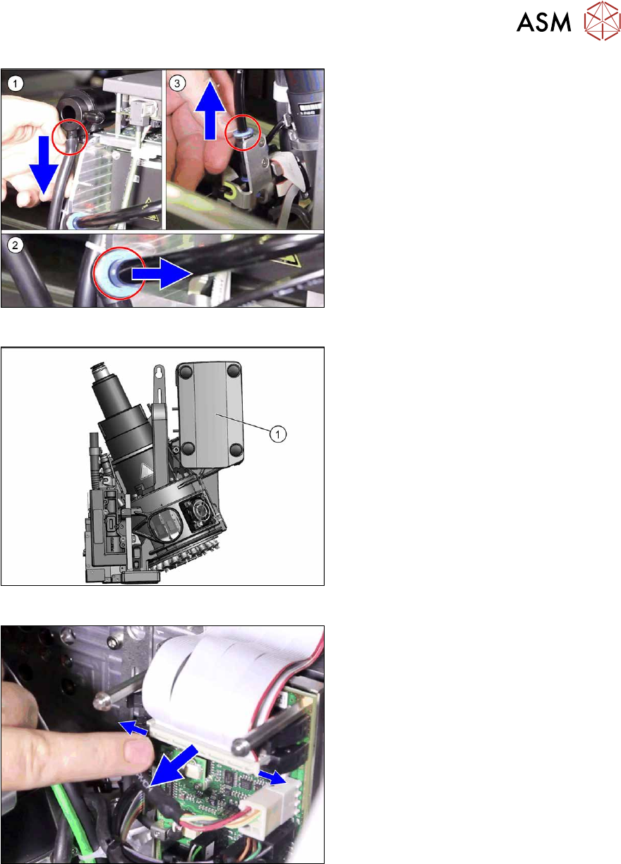
Fig.348: Pneumatic connections
► Disconnect the pneumatic connec-
tions(1)
to(3) from the placement
head.
Fig.349: Cover on intermediate distributor board
► Remove the cover(1) (press studs).
Fig.350: Flat ribbon cable
► Unplug the ribbon cables between the
placement head and the head adapter.
► Open the cable holders and unplug the PCB camera cable from the Vision Head Interface.
While unplugging the cables, press the clamps on both sides of the connectors and open any
cable ties.
► Unscrew all four M4 fastening screws with a long Torx key.
► Carefully lift the placement head out of the locating pins on the head plate and from the hook.
► Placing the head into the head transport box
► If you need to perform further work on this placement head (e.g. replacing spare parts), fit the
placement head to the head mount [03056231-xx].