00198829-01_SM_X-Series-S_Hxxxx_EN.pdf - 第265页
8 Head exchange 8.6 Replacing the SIPLACE C&P20P2 Service Manual SIPLACE X-Series S (from Hxxxx) 01/2021 265 8.6 Replacing the SIPLACE C&P20P2 NOTICE Retrofitting the SIPLACE C&P20 P2 The SIPLACE C&P20…

8 Head exchange
8.5 Replacing the SIPLACE C&P20P/M2
264 Service Manual SIPLACE X-Series S (from Hxxxx) 01/2021
Installation
► If you replace the placement head without the component camera, you will need to fit the old
camera into the new head. In this case a full calibration is necessary. Read the service
manual for your placement head for more information.
► The placement head must be converted using the "Holding circuit assembly/C&P20" kit
[03005123Sxx] or the "Compressed air mode CP20x" kit [03106765‑xx] for compressed air
mode.
► Make sure that the assembly position on the head plate is correct.
► Tighten the four head fastening screws (M4) with a torque of 2.7 Nm.
NOTICE
Various hose lengths on SIPLACE X-Series S
The hose to the pressure control valve will vary in length, depending on the installation loc-
ation (standard gantry or rotated gantry).
► Shorten or replace the hose, where necessary.
Follow the removal instructions in reverse order for further installation.
See also
2 8.9 "Installation Positions on the Head Plate" [}278]
8 Head exchange
8.6 Replacing the SIPLACE C&P20P2
Service Manual SIPLACE X-Series S (from Hxxxx) 01/2021 265
8.6 Replacing the SIPLACE C&P20P2
NOTICE
Retrofitting the SIPLACE C&P20 P2
The SIPLACE C&P20P2 can be retrofitted from machine numbers H1440.
The following prerequisites must be fulfilled:
► The head interface [03091013‑xx] / [03091023‑xx] must have at least FS04.
► The gantry sensor [03071974‑xx] must have at least FS02.
► The MGCU-3 [03103477-xx] must have at least FS04.
► The MGCU-2 [03117531‑xx] must have at least FS03.
► An X-FCU with 80 MHz [03170613-xx] must be fitted.
Parts
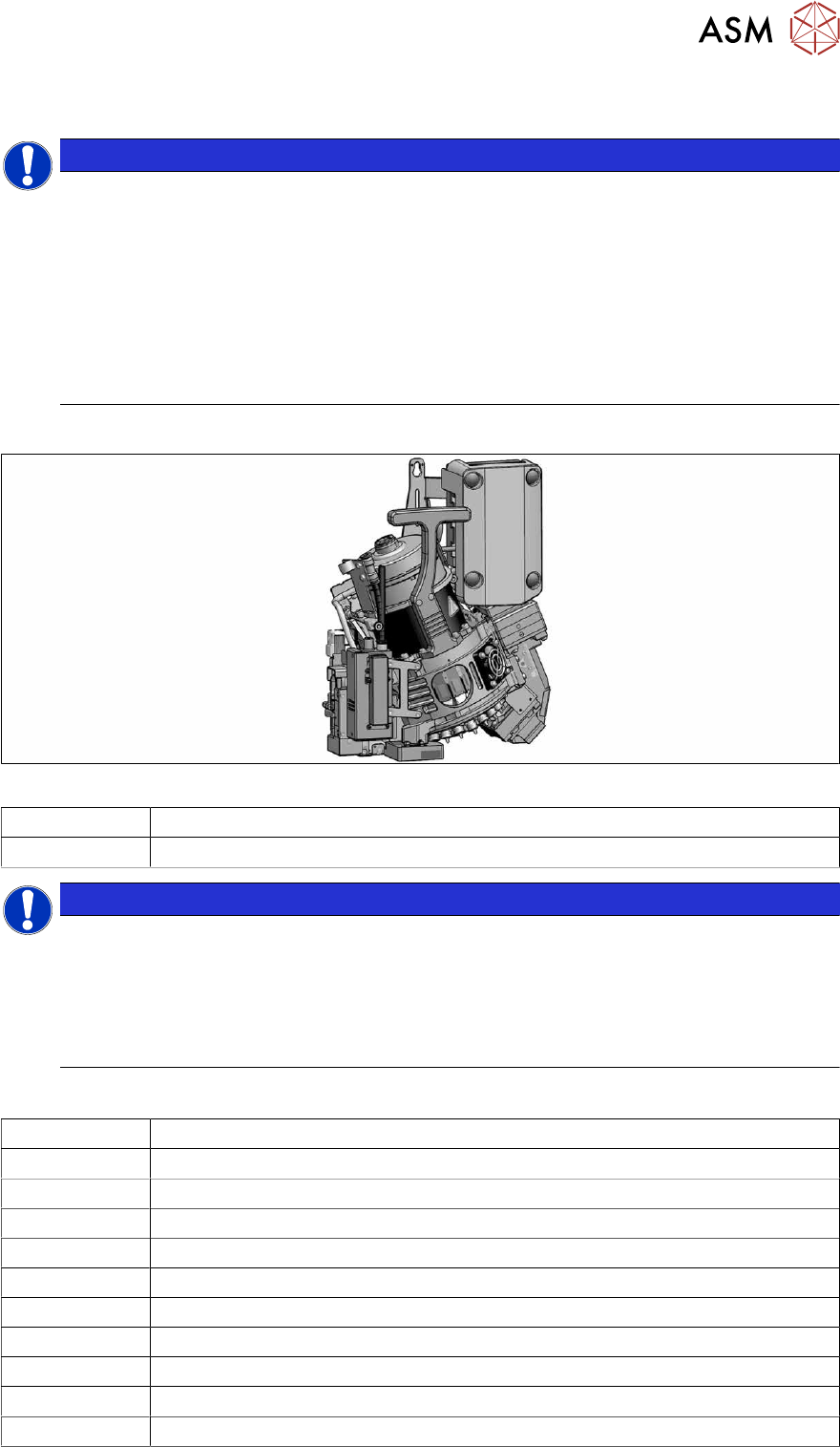
Fig.351: SIPLACE C&P20P2 with camera
03147200-xx SIPLACE C&P20P2 placement head with camera
03126608-xx SIPLACE C&P20P2 placement head without camera
NOTICE
Vacuum pump/compressed air operation
As a spare part, the head is prepared for vacuum pump operation and is fitted with the
"Aperture ring assembly C&P20 P" [03116883‑xx].
► The SIPLACE C&P20P2 must be converted with the conversion kit "Compressed air
C&P20x" [03106765‑xx] or with the "Holding circuit assembly C&P20" [03005123Sxx]
for operation in compressed air mode.
Equipment and tools
03078400‑xx Torque screwdriver ESD 1.0-5.0 Nm
03078706‑xx Bitholder for screwdriver TorqueVario
03073256‑xx Extension/ straight TX20
03156306-xx Component sensor protective cap
03157023‑xx Calibration piece SST48/49
03034148-xx Calibration part version SST23
03162648-xx Packaging SIPLACE C&P20 P2 assembly (transport box)
00198607-xx Service manual "SIPLACE C&P20P2 head"
00353832-xx Allen key set
Wire cutters
Cable tie
8 Head exchange
8.6 Replacing the SIPLACE C&P20P2
266 Service Manual SIPLACE X-Series S (from Hxxxx) 01/2021
For additional work to the placement head:
03056231‑xx Head mount
For vacuum pump operation:
00198599‑xx Vacuum pump operation: assembly instructions "Vacuum pump SIPLACE X-
Series S option from Hxxxx"
Hoses, if required:
03006727‑xx Silicone hose Di 8 Da 12 conductive (for exhaust air hose C&P20P2 295mm
[03138202‑xx])
03178204‑xx 83mm
03055411-xx Plastic hose PUN-CM-6-SW anti-static (for hose to machine for C&P20P2
[03154803‑xx])
00359177‑xx Hose 4*2.5 PUN-CM-4 (for return cylinder hose C&P20P2 135mm
[03154509‑xx])
Removal
NOTICE
Vacuum test
► If required, perform a vacuum test before removing the placement head.
Read the "Service manual Vacuum test at C&P placement head" [DE+EN:
00196101‑xx] for this.
NOTICE
Fast Hardware Exchange (FHE)
► Observe the instructions in section 8.1 "Fast Hardware Exchange" [}253] when ex-
changing a head.
► Switch off the machine, disconnect it from the power supply and secure it to prevent
unauthorized reactivation.
1.2 "Preparatory work..." [}16]
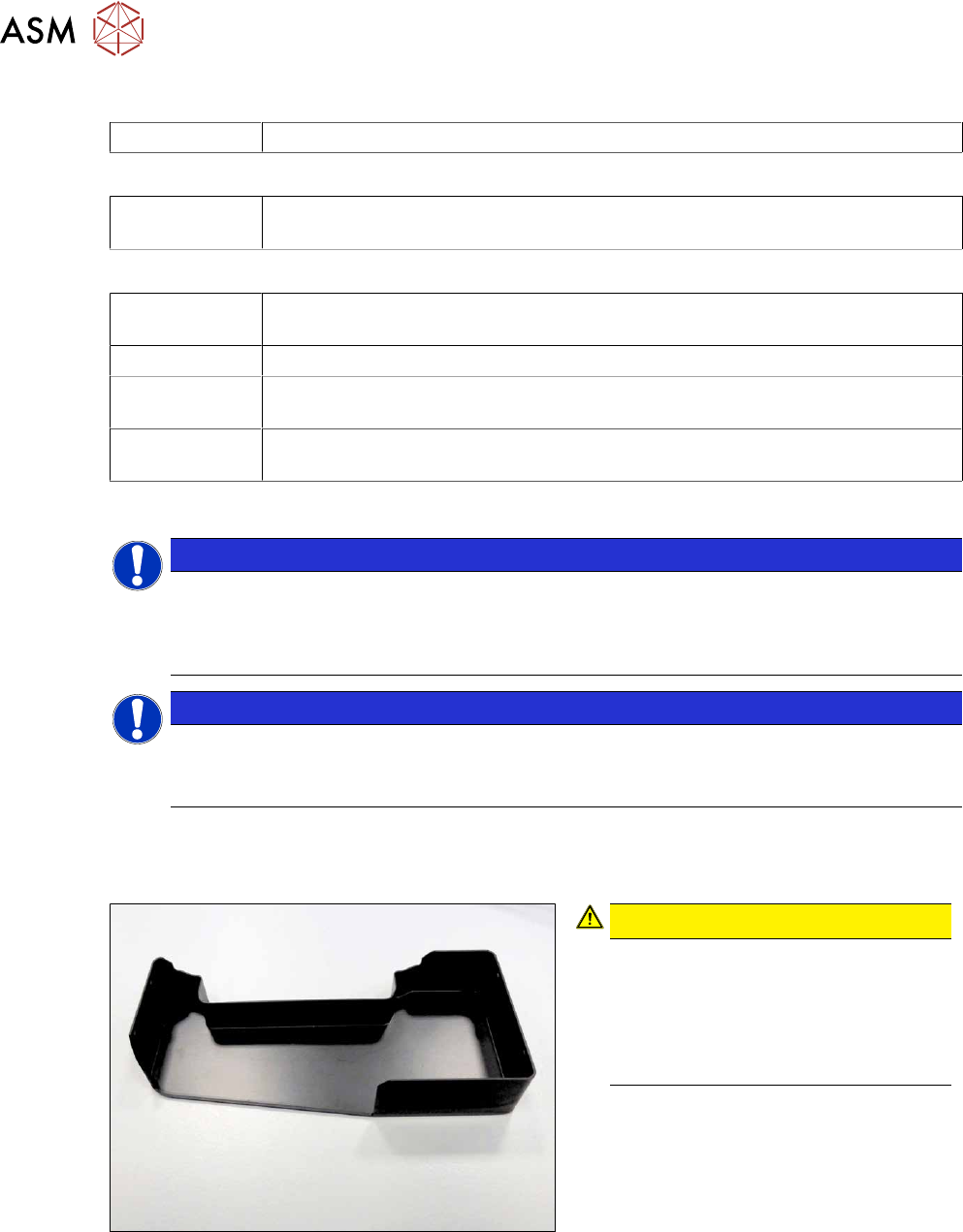
Fig.352: Component sensor protective cap
CAUTION!
Component sensor!
The component sensor prisms, under-
neath the placement head, are highly
sensitive.
Never place the placement head down
on the component sensor.
.
► Fit the protective cap onto the compo-
nent sensor for the placement head.