00198829-01_SM_X-Series-S_Hxxxx_EN.pdf - 第267页
8 Head exchange 8.6 Replacing the SIPLACE C&P20P2 Service Manual SIPLACE X-Series S (from Hxxxx) 01/2021 267 Fig.353: Electrical connections ► Open the cable ties and unplug the electrical connections (1) from the…
8 Head exchange
8.6 Replacing the SIPLACE C&P20P2
266 Service Manual SIPLACE X-Series S (from Hxxxx) 01/2021
For additional work to the placement head:
03056231‑xx Head mount
For vacuum pump operation:
00198599‑xx Vacuum pump operation: assembly instructions "Vacuum pump SIPLACE X-
Series S option from Hxxxx"
Hoses, if required:
03006727‑xx Silicone hose Di 8 Da 12 conductive (for exhaust air hose C&P20P2 295mm
[03138202‑xx])
03178204‑xx 83mm
03055411-xx Plastic hose PUN-CM-6-SW anti-static (for hose to machine for C&P20P2
[03154803‑xx])
00359177‑xx Hose 4*2.5 PUN-CM-4 (for return cylinder hose C&P20P2 135mm
[03154509‑xx])
Removal
NOTICE
Vacuum test
► If required, perform a vacuum test before removing the placement head.
Read the "Service manual Vacuum test at C&P placement head" [DE+EN:
00196101‑xx] for this.
NOTICE
Fast Hardware Exchange (FHE)
► Observe the instructions in section 8.1 "Fast Hardware Exchange" [}253] when ex-
changing a head.
► Switch off the machine, disconnect it from the power supply and secure it to prevent
unauthorized reactivation.
1.2 "Preparatory work..." [}16]
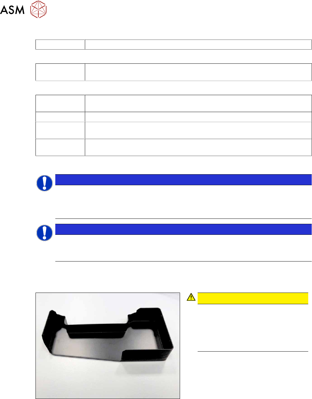
Fig.352: Component sensor protective cap
CAUTION!
Component sensor!
The component sensor prisms, under-
neath the placement head, are highly
sensitive.
Never place the placement head down
on the component sensor.
.
► Fit the protective cap onto the compo-
nent sensor for the placement head.
8 Head exchange
8.6 Replacing the SIPLACE C&P20P2
Service Manual SIPLACE X-Series S (from Hxxxx) 01/2021 267
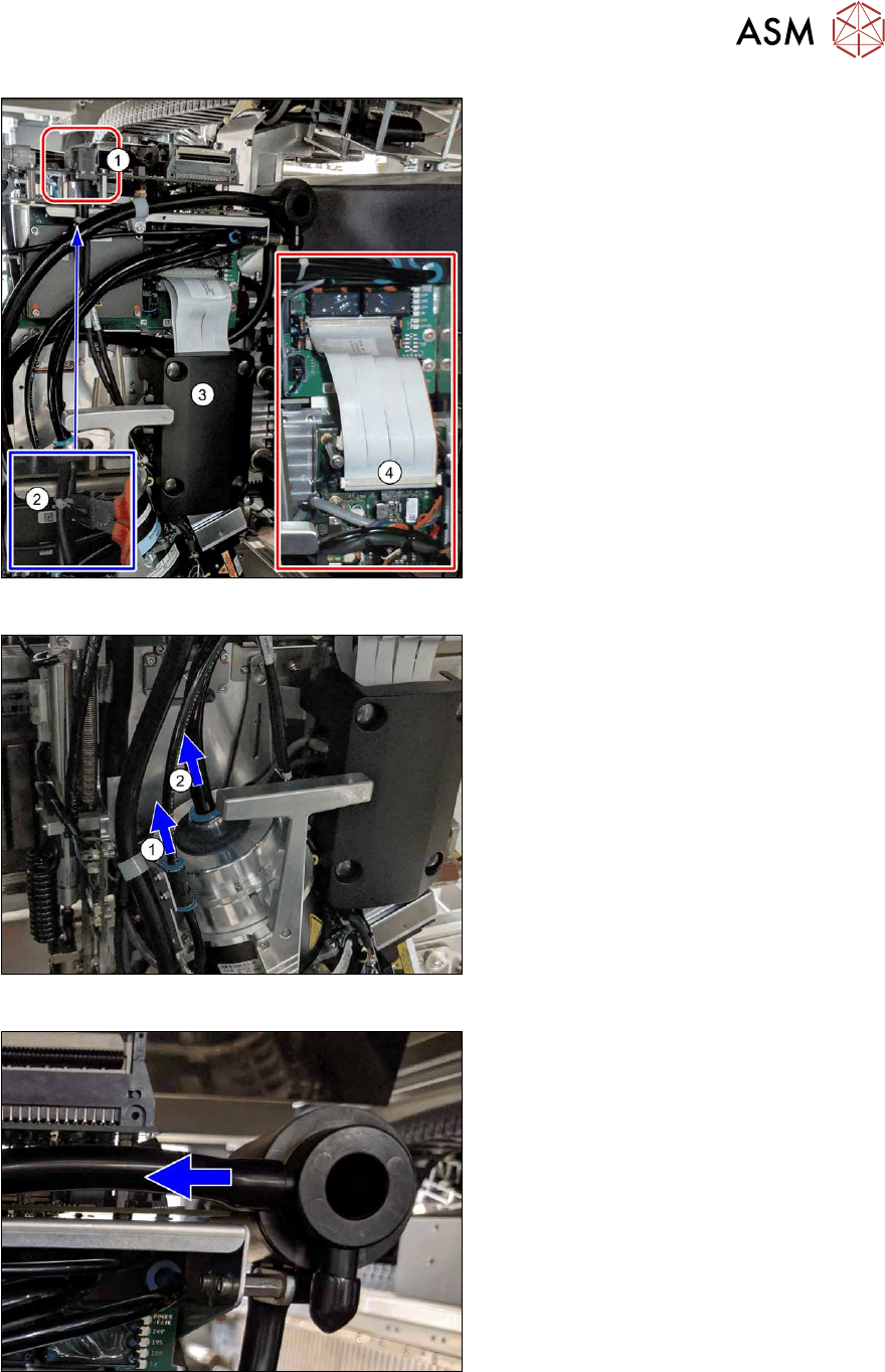
Fig.353: Electrical connections
► Open the cable ties and unplug the
electrical connections(1)
from the Vis-
ion Head Interface.
Open the cable ties, if needed(2)
.
► Pull the plastic cover(3) over the inter-
mediate distributor and off (press
studs).
► Disconnect the two flat ribbon
cables(4)
from the intermediate distrib-
utor.
Fig.354: Pulling off the hoses
► Pull the hose(1) off.
► Pull the hose(2) off the holding circuit
connection.
Fig.355: Exhaust air hose
► Pull the exhaust air hose on the filter
off.
8 Head exchange
8.6 Replacing the SIPLACE C&P20P2
268 Service Manual SIPLACE X-Series S (from Hxxxx) 01/2021
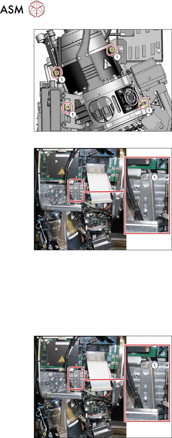
Fig.356: Fastening screws
► Unscrew all four screws(1) (M4)
fastening the heads with a long Allen
key.
These four screws are captive screws
which remain on the head.
Fig.357: Fastening screws
► Carefully lift the placement head out of
the locating pins on the head plate and
off the hook(1)
.
► Placing the head into the head transport box
Installation
► For compressed air mode, the placement head must be converted using the "Hold circuit
assembly/C&P20" [03005123Sxx].
► If you replace the placement head without the component camera, then you will need to fit the
old camera into the new head. Read the service manual for your placement head for more in-
formation.
In this case a full calibration is necessary after fitting.
Fig.358: Fastening screws
► Carefully hang the placement head on
the hook(1)
.
► Lift the placement head slightly, so that
you can thread it into the locating pins
on the head plate.