00198829-01_SM_X-Series-S_Hxxxx_EN.pdf - 第275页
8 Head exchange 8.8 Replacing the SIPLACE Twin Service Manual SIPLACE X-Series S (from Hxxxx) 01/2021 275 Overview The Twin consists of two identical Twin modules (segments), which are fitted at an angle of 180°. NOTICE …
8 Head exchange
8.8 Replacing the SIPLACE Twin
274 Service Manual SIPLACE X-Series S (from Hxxxx) 01/2021
Conversion to another installation height
Fig.368: Conversion
1. Hole for the fastening screw of the
bushing in "head at bottom" position
2. Hole for the fastening screw of the
bushing in "head at top" position
3. Bushing
All four bushings and the retaining plate
must either be fixed in top or bottom posi-
tion.
Proceed as follows when replacing the
bushings:
► Undo the fastening screws of the bush-
ings.
► Insert the bushings in the correct posi-
tion and re-tighten them.
► Perform these steps for all four fasten-
ing bushings and the retaining plate for
the head.
8.8 Replacing the SIPLACE Twin
Parts, equipment and tools
●
Select the relevant placement head:
– Twin Pick&Place module [03033628-xx]
– Twin Pick&Place module THK R2 [03097485-xx]
●
Torque screwdriver 1-5 Nm [03078400-xx]
●
Extension/straight TX20 [03073256-xx]
●
Extension/straight [03043440-xx]
●
Bit holder for Torque Vario-S screwdriver [03078706-xx]
●
Calibration tool version 3 [03010565-xx]
For additional work to the placement head:
●
Head mount [03056231‑xx]
●
Service manual "SIPLACE Twin" [DE:00197468‑xx] [EN:00197469‑xx]
●
Job Card "Preventive Maintenance Twin" [DE:00197604‑xx] [EN:00197603‑xx] (other lan-
guages available)
8 Head exchange
8.8 Replacing the SIPLACE Twin
Service Manual SIPLACE X-Series S (from Hxxxx) 01/2021 275
Overview
The Twin consists of two identical Twin modules (segments), which are fitted at an angle of 180°.
NOTICE
Module 1 and 2
The removal procedure is described here for module1 (left). Removal for module 2 (right)
is the same.
► In the case of older Twin modules, you might need to remove module 2 before remov-
ing module 1. During installation, you would then need to fit module 1 before fitting
module 2.
► In the case of newer Twin modules, the modules can be removed and fitted individu-
ally.
Fig.369: Captive screws
NOTICE!
When using modules with captive
screws(1)
you may need to fit these
screws on the other side
depending on
the installation position.
.
Observe the various different hose lengths:
Designation Item no. Length
Other hoses on the machine:
Hose supplied "silicone hose. Di8 Da12 electrically conduct-
ive 1m"
03006727Sxx
●
Cooling air hose X motor 03006777-xx 180 mm
●
Cooling air hose P+P module right 03006779-xx 395 mm
●
Cooling air hose P+P module left 03006780-xx 230 mm
●
Cooling air hose X motor TX 03126503-xx 210 mm
●
Cooling air hose X motor rotated gantry 03059420-xx 440 mm
8 Head exchange
8.8 Replacing the SIPLACE Twin
276 Service Manual SIPLACE X-Series S (from Hxxxx) 01/2021
Removal
► Switch off the machine, disconnect it from the power supply and secure it to prevent
unauthorized reactivation.
1.2 "Preparatory work..." [}16]
► Switch off the compressed air supply
5.2 "Disabling the compressed air supply" [}86]
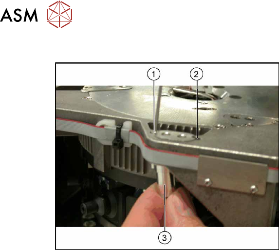
Fig.370: Connections (example of SIPLACE SX1 shown)
► Move the gantry into a position which
allows you best access.
► Unplug the pneumatic connection from
the Twin vacuum generator to the
pneumatic distributor(1)
and from the
silencer.
► Disconnect the exhaust air silicone
hose from the Twin vacuum generator
(4)
.
► Unplug the pneumatic connection from
the pneumatic distributor(1)
to the
Twin return cylinder.
► Unplug the flat ribbon cable(2) from
the head main board(3)
on the Twin.
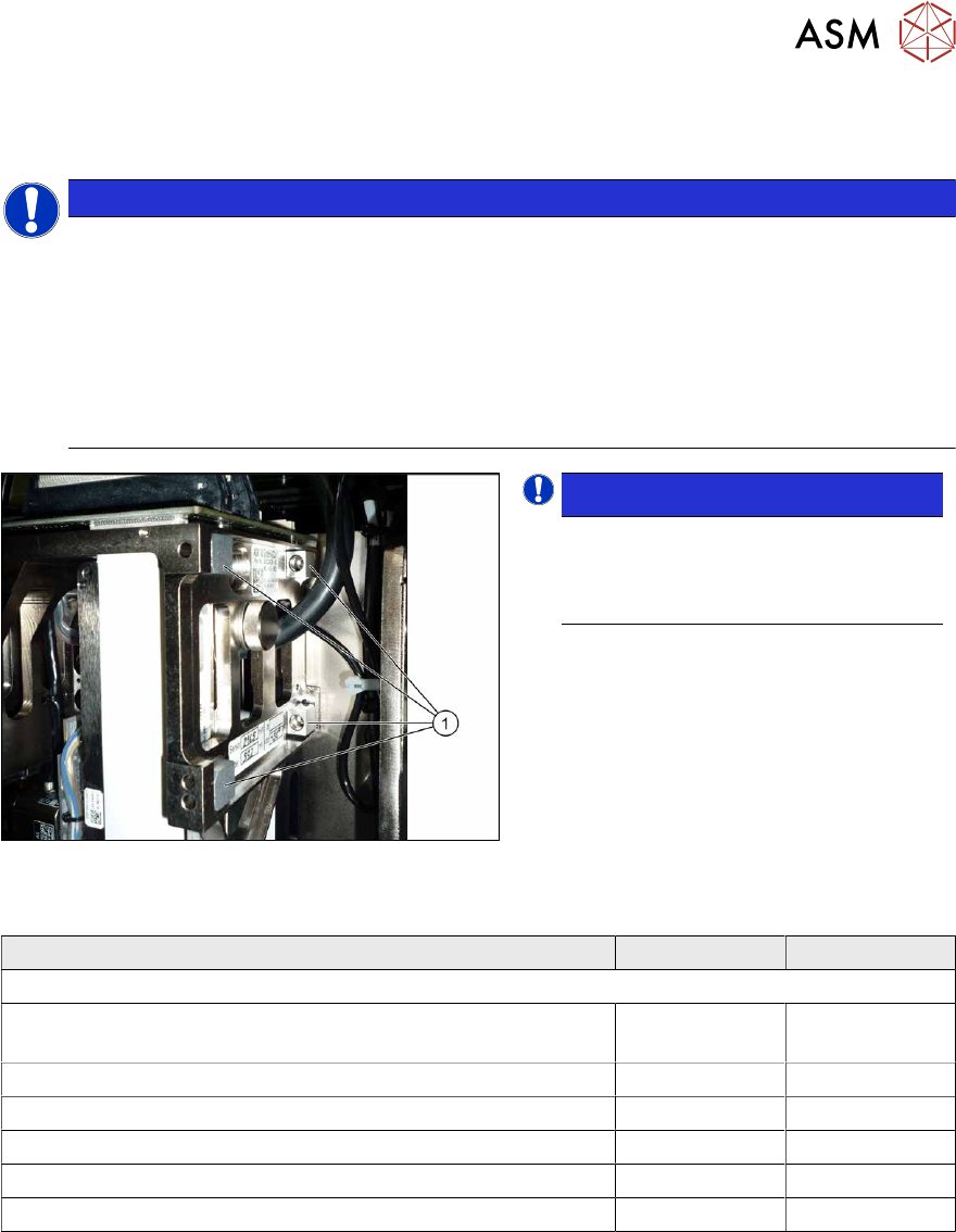
Fig.371: Camera lens hood
► Remove the camera screen(1). This is
fastened with two black screws(2)
.
NOTICE!
Only use these black screws to fix the
camera lens hood. This prevents re-
flection when measuring components
with the stationary camera.
.
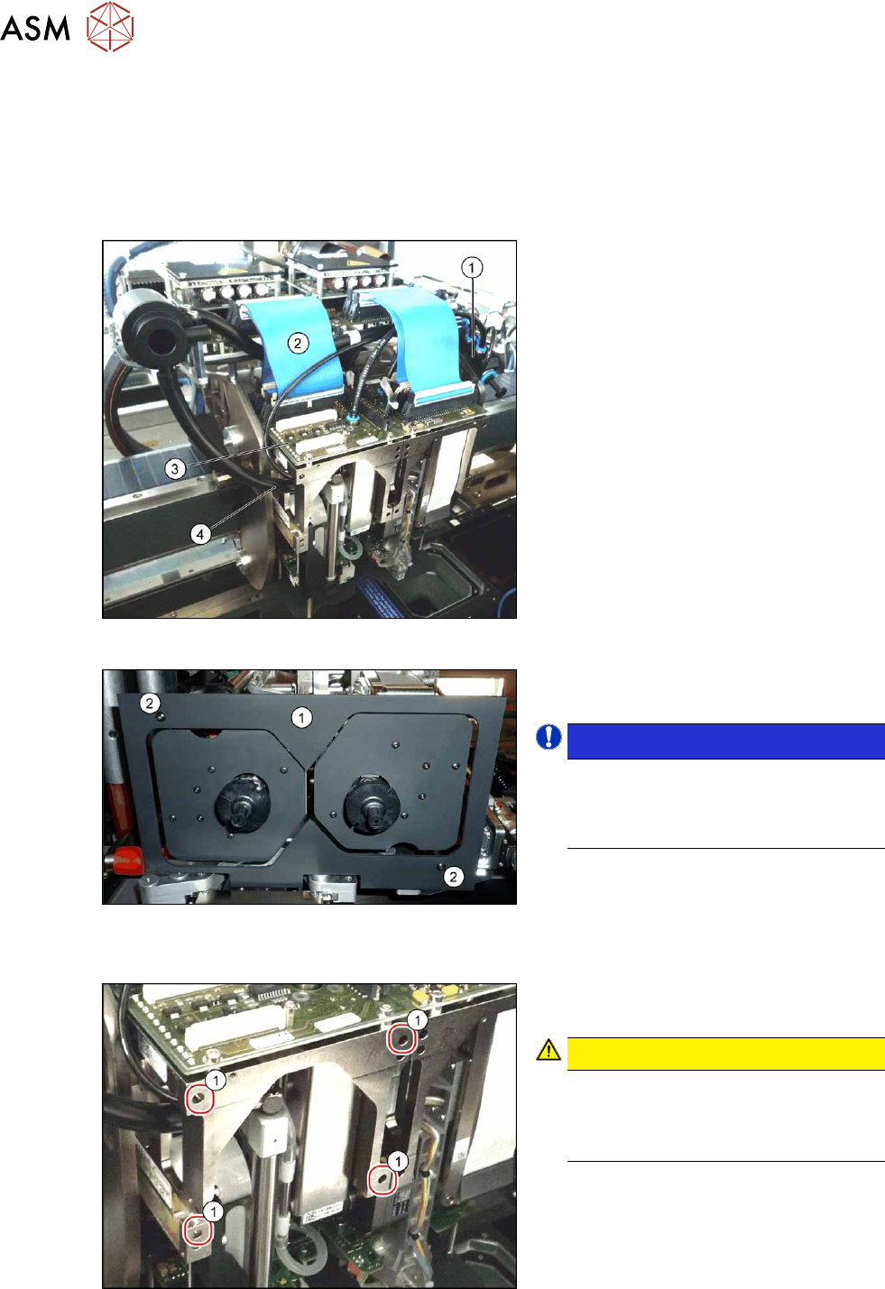
Each module is fixed with four screws (TX20) to the head plate and is positioned with two pins.
Fig.372: Fastening screws
► Unscrew the first three fastening
screws.
CAUTION!
Hold tight!
Hold the module tight before removing
the last of the four screws. The module
could otherwise fall down.
.
► Unscrew the fourth fastening screw and
pull the module out of the pins.