00198829-01_SM_X-Series-S_Hxxxx_EN.pdf - 第278页
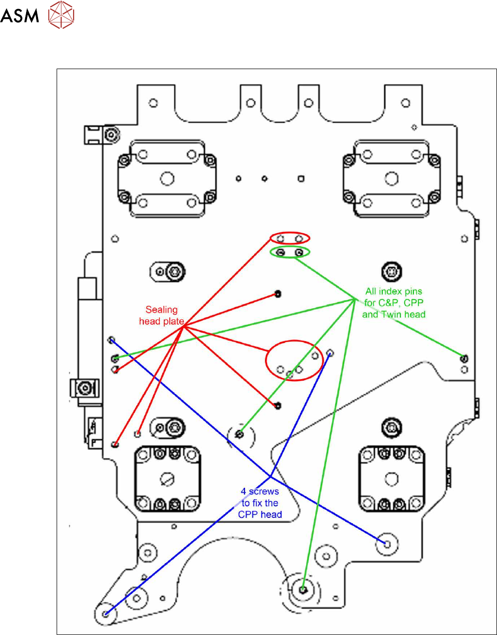
8 Head exchange 8.9 Installation Positions on the Head Plate 278 Service Manual SIPLACE X-Series S (from Hxxxx) 01/2021 8.9 Installation Positions on the Head Plate Fig.373: Installation positions on the head plate

8 Head exchange
8.8 Replacing the SIPLACE Twin
Service Manual SIPLACE X-Series S (from Hxxxx) 01/2021 277
► Placing the head into the head transport box
► If you need to perform further work on this placement head (e.g. replacing spare parts), fit the
placement head to the head mount [03056231-xx].
Installation
Follow the removal instructions in reverse order for installation. Also observe the following instruc-
tions:
► Fit the fastening screws on the other side of the module, if needed (see above).
► Make a note of the force values for the new module. These force values can be found on a
label at the side of the module.
► Make sure that the assembly position is correct.
► Perform a head calibration.
See also
2 8.9 "Installation Positions on the Head Plate" [}278]
2 8.10 "Calibration" [}279]
8 Head exchange
8.9 Installation Positions on the Head Plate
278 Service Manual SIPLACE X-Series S (from Hxxxx) 01/2021
8.9 Installation Positions on the Head Plate
Fig.373: Installation positions on the head plate
8 Head exchange
8.10 Calibration
Service Manual SIPLACE X-Series S (from Hxxxx) 01/2021 279
8.10 Calibration
Overview
The following values are determined during calibration of the component camera:
●
Relation of camera pixel size to resolution of machine measurement system (X, Y).
●
The camera center point in the X and Y directions
●
Rotation angle of the CCD sensor in the camera
This is following by determining the head offset and the segment offsets for the top and bottom.
●
Head offset: the head offset is the distance between the PCB camera and the nozzle (seg-
ment1). The target is a fixed value (X=0 and Y=‑105mm) to which an offset value (from the
head calibration) is added.
●
Segment offset top: the top segment offset involves turning the calibration tool in the compo-
nent camera in 0°, 90°, 180° and 270°. The value determined is that of the rotating center of
the nozzle tip in relation to the component camera center in the X and Y direction.
●
Segment offset bottom: the bottom segment offset involves recording and measuring the
calibration tool in the 0°, 90°, 180° and 270° positions. The value determined is that of the ro-
tating center point of the nozzle tip when the Z Axis is extended in relation to the PCB camera.
Segment1 forms the reference (X=0,Y=0) to the other segments.
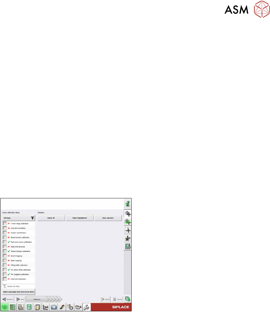
8.10.1 Calibration procedure
Fig.374: Calibration – all steps
All steps
●
Calibrating the travel range
●
Calibrating the axis zero point
●
System identification
●
Calibrating the PCB camera
●
Calibrating the PCB reference corner
●
Head and cameras
●
Calibrating the nozzle changer
●
Board mapping
●
Head mapping
●
Calibrating the lifting table
●
Pin picker, calibrating the offset
●
Calibrating the pin magazine
●
Calibrating the feed unit
Detailed procedure
► Calibrating the travel range
– Calibrating the min/max gantry travel distances
► Calibrating the axis zero point
► System identification
– Determining the moving load, friction and force constant for the selected axis to achieve a
better position for the axis.
► Calibrating the PCB camera
– Camera coefficient (illustration scale in nm/pixel)
– Calibrating the PCB camera center point
– Calibrating the PCB camera rotation to machine coordinate system
► Calibrating the PCB reference corner