00198829-01_SM_X-Series-S_Hxxxx_EN.pdf - 第298页
9 Component feeding 9.1 Cutter 298 Service Manual SIPLACE X-Series S (from Hxxxx) 01/2021 Brush Cloth Two large parallel clamps and a sturdy table with even surface, to clamp down the dismantled cutter 00353832-xx Allen …
9 Component feeding
9.1 Cutter
Service Manual SIPLACE X-Series S (from Hxxxx) 01/2021 297
9.1.10 Replacing the Cutter Blades
CAUTION
Risk of injury!
There is a high risk of injury from the blades and the wiper.
► Wear appropriately thick protective gloves!
► Never reach into the cutter from below or into the empty-tape duct from above.
► Make sure that no-one can injure themselves on the cutter after it has been dis-
mantled and placed next to the machine!
Parts
NOTICE
Turn the blade
The fixed and movable blades have been sharpened on both sides. If one side becomes
blunt, you can rotate the blade by 180 degrees to use the other side.
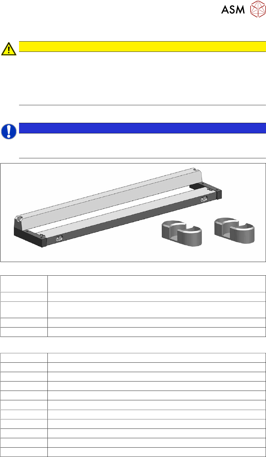
Fig.406: Set of blades and two blade covers
03009259-xx Set of blades aligned (tape cutter HF) (fits TX tape cutter, pneumatic
[03066690‑xx])
03000553-xx 2x blade cover (tape cutter HF) (cover for screws of movable blades)
03057290‑xx 2x hexagon socket fillister head screws ISO4762-M5x35-12.9, geomet 321+VL
(screws for movable blade)
03000518-xx 2x articulated joint (cutter HF)
03036943-xx 2x DIN71412-BM6 (lubrication nipple)
Equipment and tools
03121952-xx Lubrication grease BEM 34-132, 400 g cartridge
03123777-xx One-hand grease gun for 400 ml cartridge
03020782-xx Interflon Fin Grease
00334892‑xx Loctite 243
00091001-xx Extra protection gloves, leather
03078400‑xx Torque screwdriver ESD 1.0-5.0 Nm
00376625‑xx Torque wrench 2.5‑25Nm
03078706‑xx Bitholder for screwdriver TorqueVario
Allen key bit size 3-6
00096290-xx Fork wrench set
00094020-xx Feeler gauge size 20 - 0.05 - 1.0 mm
9 Component feeding
9.1 Cutter
298 Service Manual SIPLACE X-Series S (from Hxxxx) 01/2021
Brush
Cloth
Two large parallel clamps and a sturdy table with even surface, to clamp down
the dismantled cutter
00353832-xx Allen key set
Wire cutters
Cable tie
Removal
► Switch off the machine, disconnect it from the power supply and secure it to prevent
unauthorized reactivation.
1.2 "Preparatory work..." [}16]
► Remove the cutter from the machine.
9.1.4 "Replacing the Cutter on the COT Insert [03066690-xx]" [}285]
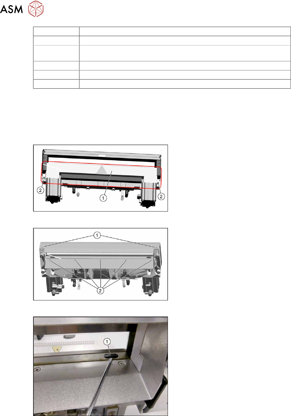
Fig.407: Cover plate
► Remove the screws(2) fastening the
top cover plate(1)
and then remove the
top cover plate.
Fig.408: Baffle plate
► Remove the two screws(1) at the front
side and five screws(2)
at the inner
side fastening the baffle plate.
► Remove the baffle plate unit from the
cutter.
Fig.409: Plastic caps
From the bottom side of the cutter you have
easy access to the plastic cap.
► Remove the plastic caps(1) over the
fastening screws on both sides of the
movable blade.
► Remove both screws.
9 Component feeding
9.1 Cutter
Service Manual SIPLACE X-Series S (from Hxxxx) 01/2021 299
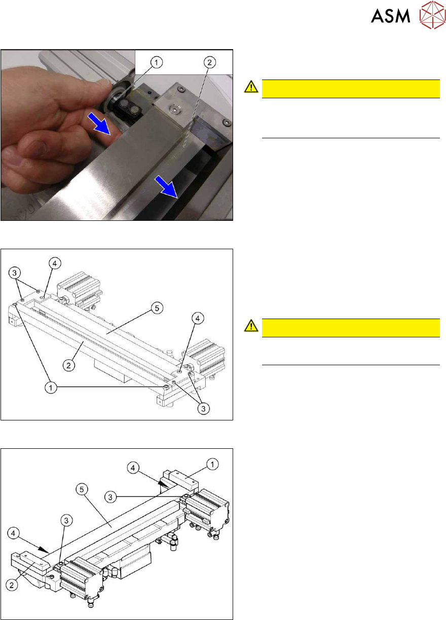
Fig.410: Movable blade
► Loosen the movable blade(2) from the
piston(1)
of the short-stroke cylinder.
CAUTION!
Risk of injury!
There is a risk of injuring yourself on
the cutting edge of the blades.
.
Fig.411: Cutter
► Remove the two screws(1) fastening
the stationary blade(2)
.
► Remove the screws fastening the left
and right wipers (3)
above the move-
able blade.
CAUTION!
Not all screws!
Do not loosen these two screws(4)
.
► Remove the wiper clip with the
wiper(5)
and carefully place the whole
unit down (with the wiper facing
upwards).
Fig.412: Cutter
► Remove the right-hand downholder(1)
and the left downholder (2), plus the
spacers below.
► Use an SW10 open-ended wrench to
push against the joint (3)
, while loosen-
ing the hexagon socket-head screw of
the joint (4)
in the moveable blade. This
may require more strength than usual
as the screws have been secured with
Loctite243.
► Grasp both ends of the moveable blade
(5)
with the protective gloves and pull it
upwards and out.