00198829-01_SM_X-Series-S_Hxxxx_EN.pdf - 第30页
2 Basic Machine 2.4 Setting the Covers 30 Service Manual SIPLACE X-Series S (from Hxxxx) 01/2021 2.4.6 Setting the Cover Rollers Fig.18: Cover rollers (example of SIPLACE SX2 shown) ► Set the cover roller by using the t…
2 Basic Machine
2.4 Setting the Covers
Service Manual SIPLACE X-Series S (from Hxxxx) 01/2021 29
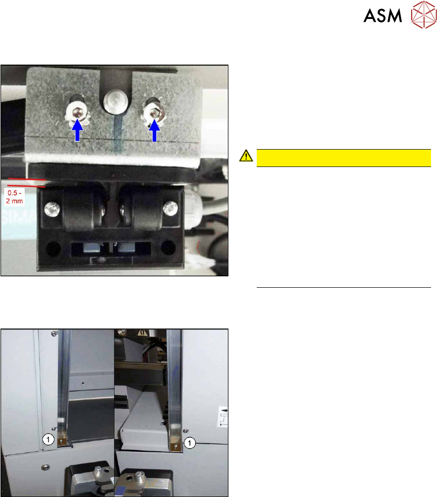
2.4.4 Setting the Actuator
Fig.16: Setting (example of SIPLACE SX2 shown)
Actuating bracket B1-2053 for AZ15/16
[00321649‑xx]
► Close the cover completely.
► Set the actuator so that it stands ap-
prox. 0.5 to 2 mm above the machine
center and tighten the screws.
CAUTION!
The cover switch is not suitable as a
stop.
The cover switch is not a stop or a
support for the cover. Use the bottom
stops of the rollers for this (see next
section).
Neither the cover nor the actuator may
be supported on the cover switch.
There must be a visible gap between
the actuator and the cover switch.
.
2.4.5 Setting the Bottom Stop
Fig.17: Bottom stop
1. 2x buffer cover guidance [03075364‑xx]
1x DIN EN ISO7380-M3 x 25-A2-70
[03045198‑xx]
1x DIN985 - M3 - A2-70 [00328897‑xx]
► Check the settings by opening and carefully closing the cover several times:
– The metal bracket is parallel to the opening and does not scrape against the switch.
– The plastic centering feature is positioned centrally to the centering device and does not
scrape against the switch.
– When the cover is opened, there is no discernable resistance of the cover rollers in the
guidance rails.
– Shortly before the bottom cover position, there is no resistance audible apart from the cen-
tering engaging and the engaging of the metal bracket in the cover switch.
– The cover can be closed completely, so that the cover closes smoothly at the top with the
side covers.
2 Basic Machine
2.4 Setting the Covers
30 Service Manual SIPLACE X-Series S (from Hxxxx) 01/2021
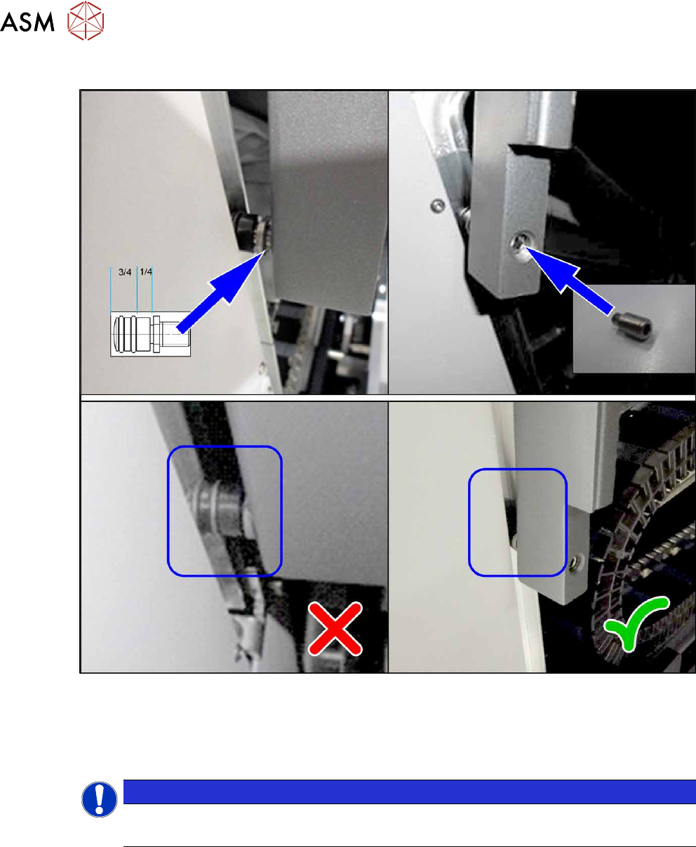
2.4.6 Setting the Cover Rollers
Fig.18: Cover rollers (example of SIPLACE SX2 shown)
► Set the cover roller by using the threaded pin, so that it is inserted by at least 75% into the
guidance, along its whole length. Lock the roller with a threaded pin DIN915-M8x16
[00304354-xx] or DIN-EN-ISO4026-M8x16-A2-21H [03025582-xx].
Place washers between the roller and cover for greater stability.
NOTICE
Missing O-rings
► Replace the following missing O-rings on the roller: O-ring 8.5x1.6 [03078577-xx]
2 Basic Machine
2.5 Replacing the barcode laminate for the X feeder
Service Manual SIPLACE X-Series S (from Hxxxx) 01/2021 31
2.5 Replacing the barcode laminate for the X feeder
Parts, equipment and tools
Select a suitable barcode laminate:
●
1D barcodes:
– Barcode laminate X feeder sector 1 SX4 [03085971-xx]
– Barcode laminate X feeder sector 2 SX4 [03085976-xx]
– Barcode laminate X feeder sector 3 SX4 [03085994-xx]
– Barcode laminate X feeder sector 4 SX4 [03085995-xx]
●
2D barcodes:
– Barcode set for 4 locations [03216618‑xx]
NOTICE!
Always replace all
If using barcode laminates with 2D barcodes, all four bar-
code laminates and all four MID labels must be replaced.
It is not possible to replace individual barcode laminates
as the MID is in the 2D barcode and this is unique.
.
You also need the following:
●
Cleaning agent
CAUTION
ESD coating
The choice of cleaning agent for the protective covers must be made with particular care so
as not to damage the ESD coating on the protective covers! Never use acid or strong al-
kaline agents and avoid all ketones, esters, aromatics, halogenated hydrocarbons, essen-
tial oils or similar.
► Only apply light pressure as you clean the protective covers so as not to damage the
ESD coating!
Removal
► Remove the old barcode laminate.
Installation
Follow the removal instructions in reverse order for installation. Also observe the following instructions:
► Make sure that the adhesive surface is clean and free of grease. Clean if necessary.
► Make sure that the tracks shown on the label match those of the table or the track label.
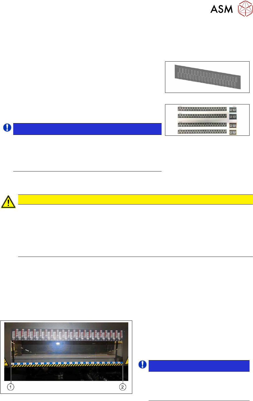
Fig.19: Positioning the barcode ruler
► The barcode ruler must be flat against
the disk on the left of all locations (1)
.
► The track ruler must always be placed
so that it indicates towards the machine
center(2)
.
NOTICE!
Recommendation
Place the two 8mm feeders on
tracks1 and40, in order to estimate
the correct position more precisely.
.