00198829-01_SM_X-Series-S_Hxxxx_EN.pdf - 第309页
9 Component feeding 9.1 Cutter Service Manual SIPLACE X-Series S (from Hxxxx) 01/2021 309 Fig.431: Measuring times To test all cutters, you can switch over to the maintenance menu: ► Select . ► Select Check tape cutter …
9 Component feeding
9.1 Cutter
308 Service Manual SIPLACE X-Series S (from Hxxxx) 01/2021
Removal
► Switch off the machine, disconnect it from the power supply and secure it to prevent
unauthorized reactivation.
1.2 "Preparatory work..." [}16]
► Switch off the compressed air supply
5.2 "Disabling the compressed air supply" [}86]
► Vent the cutter. It must be totally depressurized.
9.1.2 "Venting compressed air at the cutter" [}284]
► Try to perform the exchange on the installed cutter.
If access is too limited, remove the cutter from the machine.
Replacing the Cutter on the COT Insert [03066690-xx]
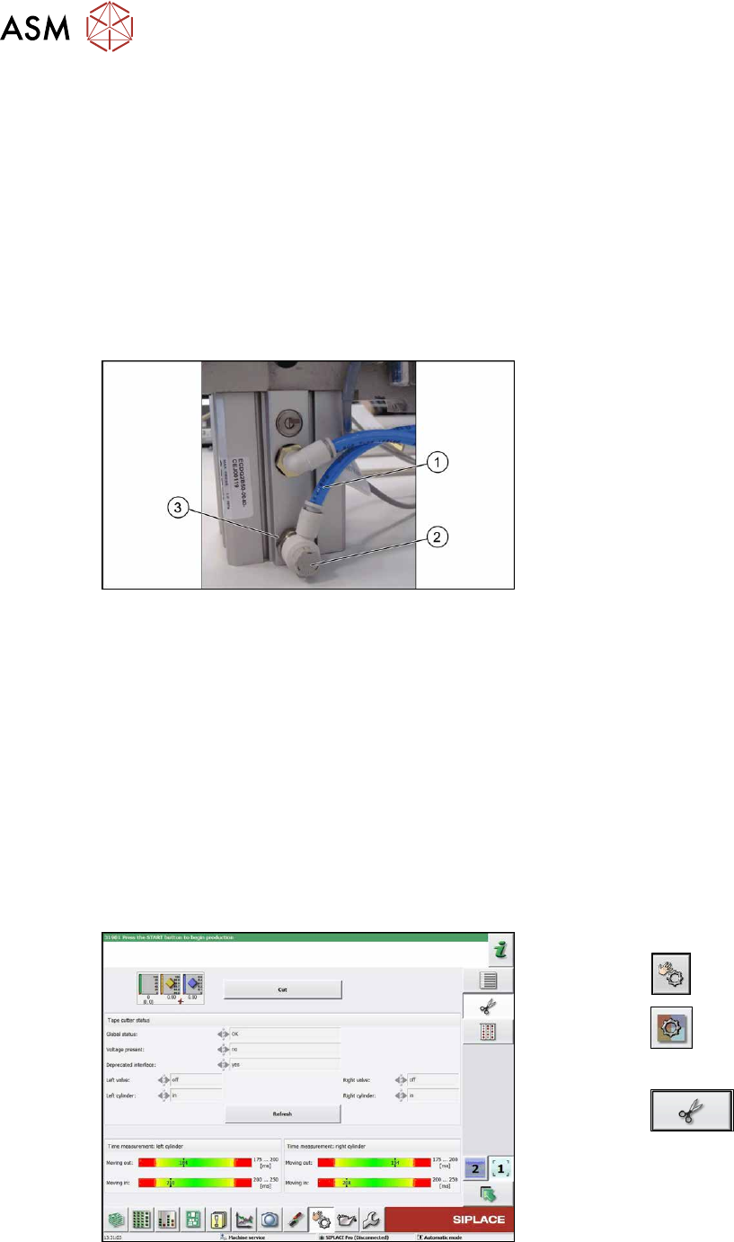
Fig.429: Removing the throttle valve
► Disconnect the air tube(1) from the
throttle valve(2)
.
► Turn the throttle valve in the direction
"-" and count the turns. Note the num-
ber.
► Remove the throttle valve by using a
SW17 spanner(3)
.
Installation
► Fit the new throttle valve. Take care of the silicon sealing.
► Close the throttle valve completely in direction "-" and open it again in direction “+” by counting
the noted turnings.
This will ensure a working pre-adjustment for starting the final setting later on.
► Connect the air tube.
Follow the removal instructions in reverse order for further installation.
► Set the new throttle valve (see below).
9.1.14.1 Times for setting the restrictor on the cutter
The menu is available from SW707.1.
Fig.430: Measuring times
► Switch over to Check sensors and
functions .
► Select the button.
► Select Location.
► Select the button.
► Select Cut to start test.
You have to select the Cut
button at
least two times (one for each side).
► Check the measured times.
► Repeat if necessary.
9 Component feeding
9.1 Cutter
Service Manual SIPLACE X-Series S (from Hxxxx) 01/2021 309
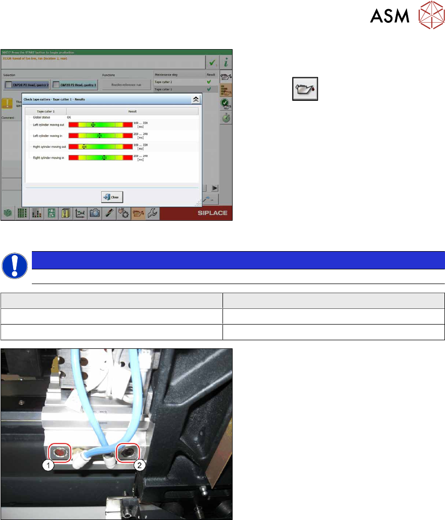
Fig.431: Measuring times
To test all cutters, you can switch over to the
maintenance menu:
► Select .
► Select Check tape cutter.
► Mark the relevant line to see the time in
the details.
NOTICE
The permitted measurement ranges will be provided by the software.
Cutter Time
Moving the blade out 175 to 200 ms
Moving the blade in 200 to 250 ms
Fig.432: Restrictor valves
► If necessary: change the time by ad-
justing the restrictor valves at the short-
stroke cylinders.
1. Infeed restrictor
2. Outfeed restrictor
See also
2 9.1.9 "Replacing the short-stroke cylinder" [}295]
9 Component feeding
9.1 Cutter
310 Service Manual SIPLACE X-Series S (from Hxxxx) 01/2021
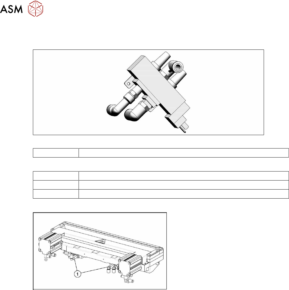
9.1.15 Replacing the solenoid valves
Parts
Fig.433: Solenoid valve
03000630-xx Solenoid valve
Equipment and tools
00353832-xx Allen key set
Wire cutters
Cable tie
Overview
Fig.434: Cutter
1. Position of the solenoid valves
Removal
► Switch off the machine, disconnect it from the power supply and secure it to prevent
unauthorized reactivation.
1.2 "Preparatory work..." [}16]
► Switch off the compressed air supply
5.2 "Disabling the compressed air supply" [}86]
► Vent the cutter. It must be totally depressurized.
9.1.2 "Venting compressed air at the cutter" [}284]
► Loosen the compressed air connections on the solenoid valve.
► Unplug the press-fit connection on the solenoid valve connection cable. Mark the position to
make clear assignment easier later on.
► Remove the screws holding the solenoid valve in place and remove the solenoid valve.
Installation
► Mount the new solenoid valve and reestablish the press-fit connection to the valve.
► Plug in the compressed air connections.
► Attach cables ties if necessary (strain relief).