00198829-01_SM_X-Series-S_Hxxxx_EN.pdf - 第312页
9 Component feeding 9.2 COT insert 312 Service Manual SIPLACE X-Series S (from Hxxxx) 01/2021 Installation Follow the removal instructions in reverse order for installation. Observe the following note: Fig.437: Push-in …
9 Component feeding
9.1 Cutter
Service Manual SIPLACE X-Series S (from Hxxxx) 01/2021 311
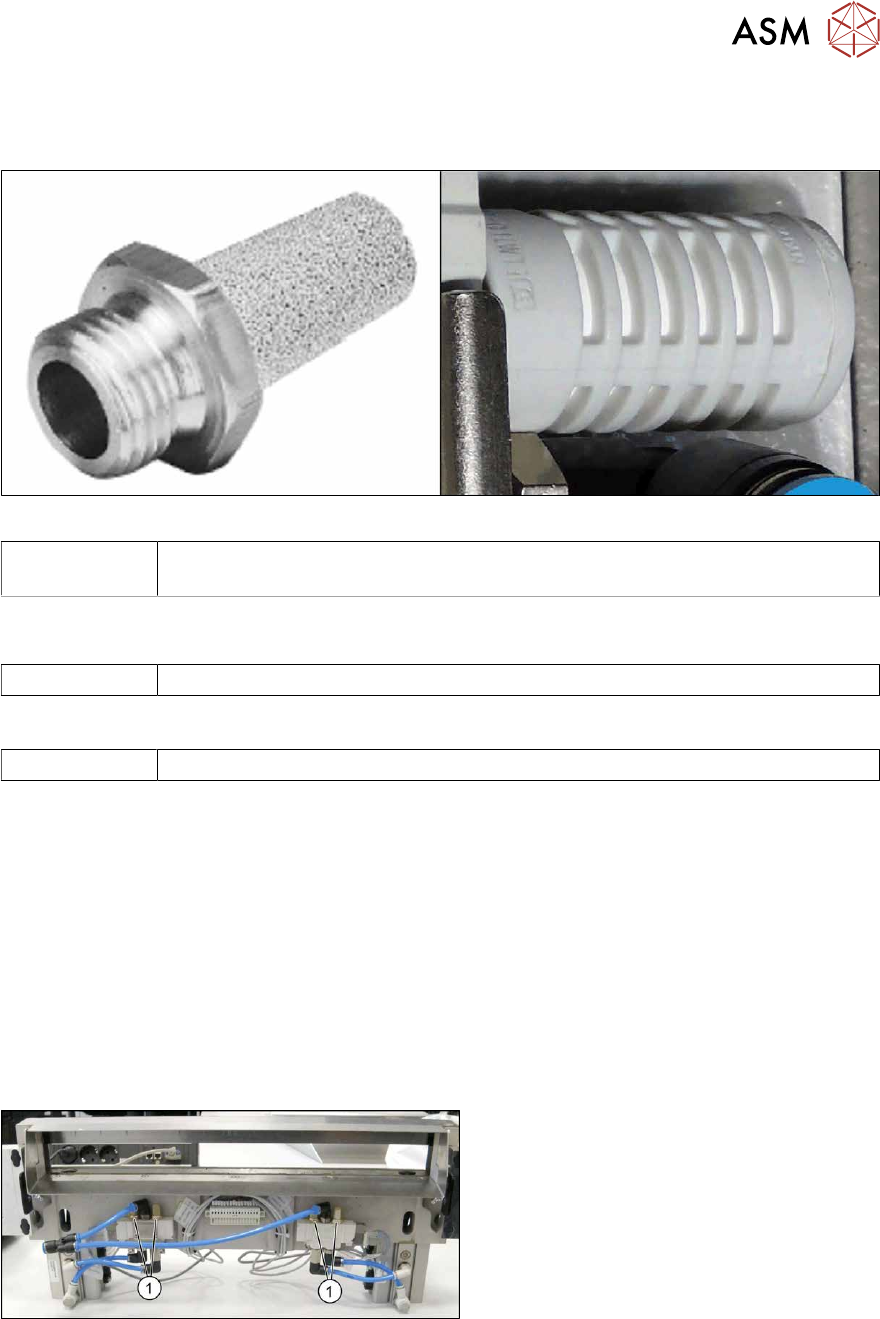
9.1.16 Replacing the silencer
Parts
Fig.435: Silencer version 1 and 2
03122731‑xx Silencer R1/8 40dB (version2)
(replaces version 1 [00317044‑xx])
If a silencer version 1 is replaced with a version 2 silencer, you will also need to use this push-in fit-
ting:
00320172-xx Push-in L-fitting QSL-1/8-6
Equipment and tools
00096290-xx Fork wrench set
Removal
► Switch off the machine, disconnect it from the power supply and secure it to prevent
unauthorized reactivation.
1.2 "Preparatory work..." [}16]
► Switch off the compressed air supply
5.2 "Disabling the compressed air supply" [}86]
► Vent the cutter. It must be totally depressurized.
9.1.2 "Venting compressed air at the cutter" [}284]
► Try to perform the exchange on the installed cutter.
If access is too limited, remove the cutter from the machine.
9.1.4 "Replacing the Cutter on the COT Insert [03066690-xx]" [}285]
Fig.436: Silencer on cutter
► Remove the silencer(1) (SW13).
9 Component feeding
9.2 COT insert
312 Service Manual SIPLACE X-Series S (from Hxxxx) 01/2021
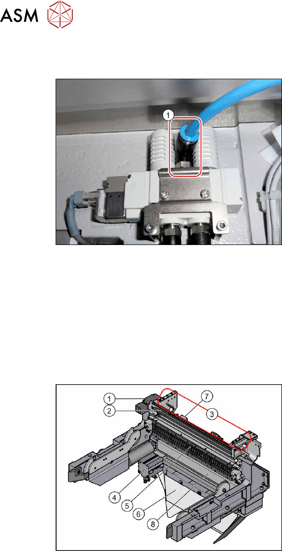
Installation
Follow the removal instructions in reverse order for installation. Observe the following note:
Fig.437: Push-in fitting
Conversion from version 1 to version
2
► If you replace a version 1 silencer with
a version 2 silencer, you will also need
to replace the push-in fitting (1)
between the two silencers for space
reasons.
– Old: [03000631‑xx] Push-in L fitting
QSL-1/8-6 (SW12)
– New: [00320172‑xx] Push-in L fitting
QSL-1/8-6 (SW10)
9.2 COT insert
See also
2 2.8.2 "Reject bin and sensors - overview" [}38]
2 2.8 "Nozzle Changers and Reject Boxes" [}36]
9.2.1 COT insert
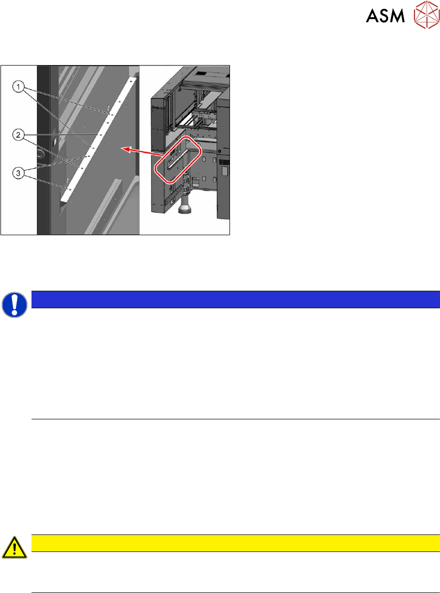
Fig.438: COT insert overview
1. Safety switch for the component trolley
2. Empty tape duct
3. Assembly positions for the nozzle
changers
4. Cutter
5. Feeder control unit (FCU)
6. Waste tape slide
7. Feed control
8. Feeder unlock device
9 Component feeding
9.2 COT insert
Service Manual SIPLACE X-Series S (from Hxxxx) 01/2021 313
9.2.2 Installation Positions of COT Insert and Manual Table (Table Positions)
Fig.439: Installation positions
The following installation positions apply to
the SIPLACE X-Series S:
1. Installation position 1
COT insert: X4i S
2. Installation position 2
COT insert, manual table: X4i S
3. Installation position 3
COT insert, manual table: X2 S, X3 S,
X4 S
9.2.3 Replacing the COT Insert Assembly
NOTICE
Working on the COT-i without complete removal of this
For some tasks on the COT-i, it may be enough to just pull the COT-i slightly out of the
machine. In this case, follow the procedure for replacement but observe the following
instructions:
► Remove the screws fastening the central unit and the lifting mechanics.
► You usually do not need to disconnect the cable. However, if the cable is too short,
unplug it.
► Slightly pull the COT-i out of the machine.
Parts, equipment and tools
●
SIPLACE X3 S, X4 S: COT insert X4 S [03098442-xx]
or
SIPLACE X4i S: COT insert X4i S [03093204-xx]
●
Circuit diagram X-Series S [00197021-xx] (German/English)
●
Mounting tool [03015976-xx]
●
Suitable lifting device (e.g. hand-operated crane)
CAUTION
Heavy machine part!
The COT insert is heavy. To lift it out, you will need to use the mounting tool and a suitable
lifting device (hand-operated crane etc.).
Removal
► Switch off the machine, disconnect it from the power supply and secure it to prevent
unauthorized reactivation.
1.2 "Preparatory work..." [}16]
► Switch off the compressed air supply
5.2 "Disabling the compressed air supply" [}86]
► Dismantle the nozzle changer.
2.8.3 "Replacing the Nozzle Changer" [}40]