00198829-01_SM_X-Series-S_Hxxxx_EN.pdf - 第323页
9 Component feeding 9.2 COT insert Service Manual SIPLACE X-Series S (from Hxxxx) 01/2021 323 9.2.9 Replacing the COT insert control valve Parts, equipment and tools ● Valve assembly SX4 [03097252-xx] Overview 1 Fig.453…

9 Component feeding
9.2 COT insert
322 Service Manual SIPLACE X-Series S (from Hxxxx) 01/2021
► Carefully lift the empty-tape duct out of the COT insert.
NOTICE
Unplug the cable from the FCU
► You could also unplug the cable at the FCU. This gives you greater freedom of move-
ment. In this case, note the positions, to make clear assignment easier later on.
CAUTION
Risk of cutting
The cutter is located under the empty tape duct. There is a very sharp blade located there.
► Do not reach into the cutter and make sure that it is never left unmonitored or freely
accessible.
Installation
Follow the removal instructions in reverse order for installation. Also observe the following instruc-
tions:
► Fit the sensors (reed contacts) for the reject container.
NOTICE
These sensors are installed in different positions, according to the configuration of
the machine.
► Refer to the appropriate assembly instructions.
► Fit the empty-tape duct.
► When fitting the nozzle changer, observe the applicable assembly instructions, as you need to
check the installation height.
9 Component feeding
9.2 COT insert
Service Manual SIPLACE X-Series S (from Hxxxx) 01/2021 323
9.2.9 Replacing the COT insert control valve
Parts, equipment and tools
●
Valve assembly SX4 [03097252-xx]
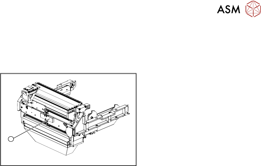
Overview
1
Fig.453: Control valve on the COT insert
► Control valve
Removal
► Switch off the machine, disconnect it from the power supply and secure it to prevent
unauthorized reactivation.
1.2 "Preparatory work..." [}16]
► Switch off the compressed air supply
5.2 "Disabling the compressed air supply" [}86]
► You may have to move out the COTi out a little to improve the accessibility.
9.2.3 "Replacing the COT Insert Assembly" [}313]
► Dismantle the cover plate over the valve.
► Disconnect the electrical and pneumatic connections to the control valve(1). Mark their posi-
tions, to make clear assignment easier later on.
► Remove the fastening screws and remove the control valve.
Installation
► Installation is performed by following the above instructions in the reverse order.
9 Component feeding
9.2 COT insert
324 Service Manual SIPLACE X-Series S (from Hxxxx) 01/2021
9.2.10 Replacing the empty tape duct Einsatz
► Read the relevant section of the user manual for your machine.
Parts, equipment and tools
●
Empty tape duct insert
(The number can be found in catalog of parts.)
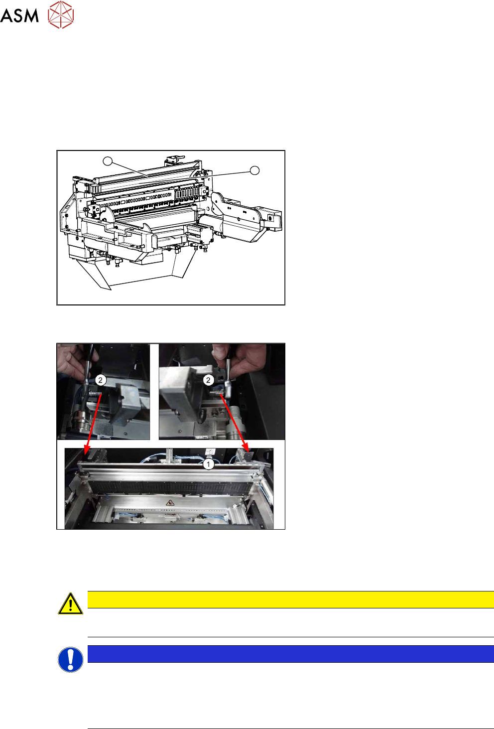
Overview
1
2
Fig.454: Empty tape duct (example of SIPLACE X‑Series
shown)
1. Empty tape duct assembly
2. Empty tape duct insert
Fig.455: Empty tape duct insert (example of SIPLACE SX4
shown)
1. Empty tape duct
2. Screws fastening the empty tape duct
insert (left and right)
Removal
CAUTION
Do not dismantle the empty tape duct
Only the empty tape duct insert may be replaced. Do not dismantle the empty tape duct.
NOTICE
Inner empty tape duct insert
When using tape reels with deep pockets, you may need to remove the inner baffle. Refer
to the operating manual of your machine for details.
All screws are accessible in the installed state. The baffles can therefore be replaced inside
the machine.
► Remove the two screws fastening the empty tape duct insert and remove these.