00198829-01_SM_X-Series-S_Hxxxx_EN.pdf - 第330页
9 Component feeding 9.3 X-Series Component Trolley 330 Service Manual SIPLACE X-Series S (from Hxxxx) 01/2021 9.3 X-Series Component Trolley 9.3.1 SIPLACE X-series component trolley 1 4 3 2 Fig.463: SIPLACE X-series com…
9 Component feeding
9.2 COT insert
Service Manual SIPLACE X-Series S (from Hxxxx) 01/2021 329
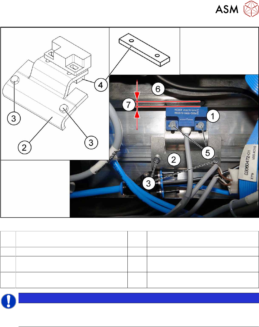
Fig.462: Sensor mount for 6x6 reject duct
1 Sensor 2 Metal sensor MK2 prefitted [03080138-
xx]
3 ISO1479-ST3.5x6.5-C [03080219-xx] 4 Bracket [03080137-xx]
5 PT screw 3.5x7-ST-10 galvanized
[03087342‑xx]
6 Component reject duct 6x6
7 The distance between the reject bin and
the sensor
NOTICE
Plastic screws
Only use the plastic screws provided to fasten the sensor (5) "PT screw 3.5x7-ST-10 gal-
vanized" [03087342‑xx]!
► Insert the reject bin 6x6.
► Use the slots to set the sensor with the bracket (4) and the plastic screws "PT screw 3.5x7-
ST-10 gal. zinc" [03087342‑xx] while the machine is running, so that it just reacts when the
reject bin is fitted (6)
. The distance (7) between the reject bin and the sensor must be 5 mm. If
the distance is less, the reject bin could then protrude, causing a head crash.
► Observe the display on the user interface while the machine is running or the LED status for
sensor S1 (right LED 1/left LED 3) in test mode on the FCU.
► The reject bin may not have more than 2 mm upwards play.
See also
2 2.8.2 "Reject bin and sensors - overview" [}38]
2 2.8 "Nozzle Changers and Reject Boxes" [}36]
9 Component feeding
9.3 X-Series Component Trolley
330 Service Manual SIPLACE X-Series S (from Hxxxx) 01/2021
9.3 X-Series Component Trolley
9.3.1 SIPLACE X-series component trolley
1
4
3
2
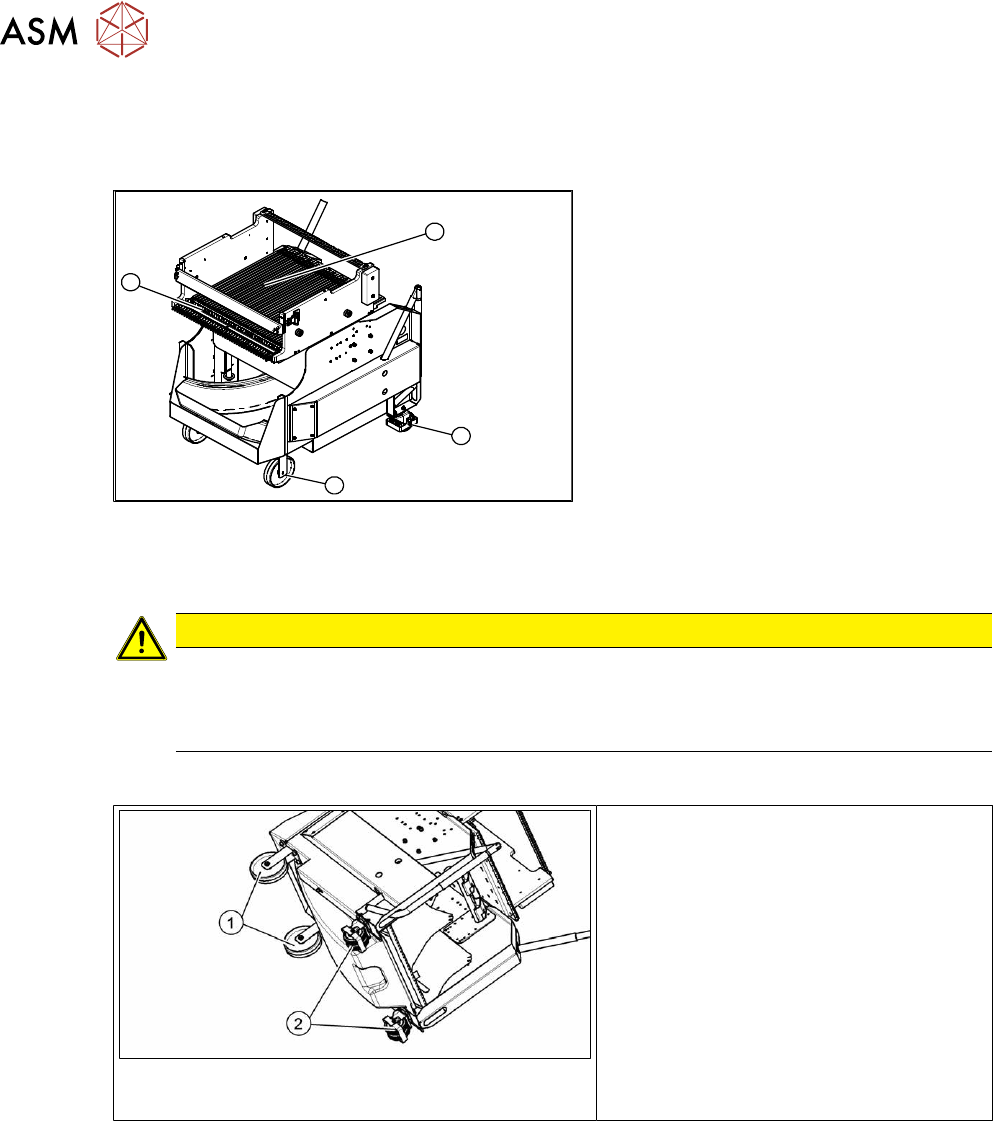
Fig.463: SIPLACE X-series component trolley
1. Guide castor
2. Fixed castor
3. Locking strip
4. Support block
9.3.2 Replacing the Fixed/Guide Castors [00341918-xx]
CAUTION
Heavy machine part!
The component trolley must be placed on one side in order to remove the fixed/guide
castors. The component changeover table is extremely heavy! You will need two people to
perform this task.
Parts, equipment and tools
Fig.464: Fixed and guide castors (example of SIPLACE
X‑Series shown)
1. Fixed castor [00341918-xx]
2. Guide castor [03004958-xx]
●
Second person
Removal/Installation
► Remove all feeders from the component trolley.
► Move the component trolley out of the machine.
► Place the component trolley down on its side, on a suitable surface.
► Remove the screws fastening the fixed/guide castor to be replaced and then remove the
castor.
► Insert the new fixed/guide castor.
► Stand the component trolley on its wheels again.
9 Component feeding
9.3 X-Series Component Trolley
Service Manual SIPLACE X-Series S (from Hxxxx) 01/2021 331
9.3.3 Replacing the locking latch
Parts
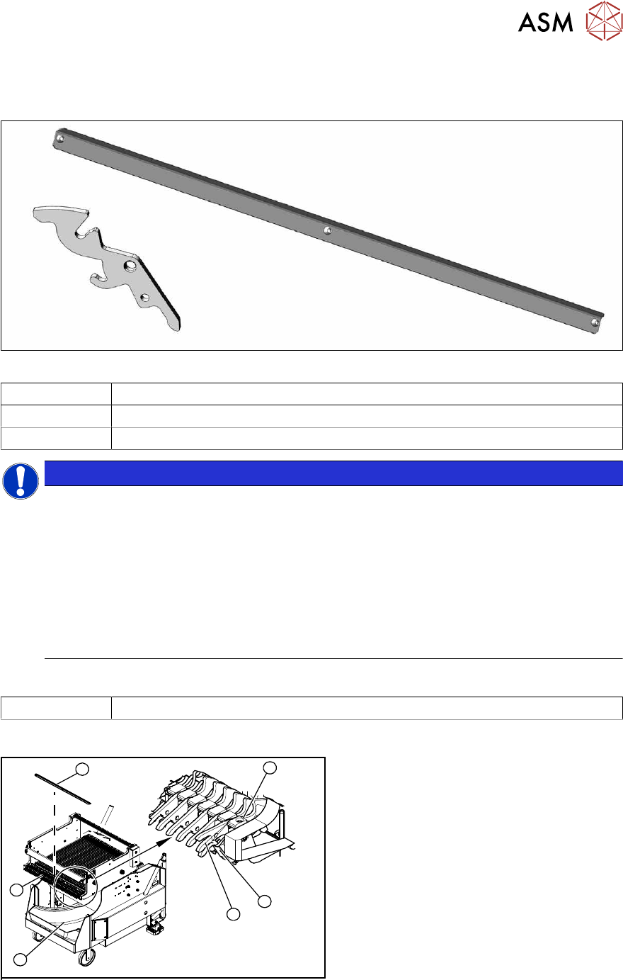
Fig.465: Locking latch and cover plate
03069205-xx Single locking latch
03077142-xx Cover plate for locking strip
03010352-xx Tension spring
NOTICE
SIPLACE TX/X/SX-Series component trolley
Component trolleys from the SIPLACE TX, SX and X-Series (S) require a locking latch for
each feeder track.
► Feeder lock [03023777-xx] with 40 locking latches
(1x per component trolley SIPLACE TX/X-Series (S)/SX4)
► Feeder lock [03057284-xx] with 30 locking latches
(1x per 30 track, 2x per 60 track component trolley SIPLACE SX1/SX2)
ð The feeder lock can also be completely dismantled from the component trolley and
replaced.
Equipment and tools
00353832-xx Allen key set
Overview
4
6
5
1
3
2
Fig.466: Locking latch on component trolley
1. Waste tape container
2. Cover
3. Position of complete feeder locking
mechanism
4. Locking latch
5. Tension spring
6. Pressure plate (under cover(2))