00198829-01_SM_X-Series-S_Hxxxx_EN.pdf - 第339页
9 Component feeding 9.4 Docking Station for Component Trolley Service Manual SIPLACE X-Series S (from Hxxxx) 01/2021 339 9.4.2 Replacing the power pack NOTICE Observing the technical information ► Observe the technical i…
9 Component feeding
9.4 Docking Station for Component Trolley
338 Service Manual SIPLACE X-Series S (from Hxxxx) 01/2021
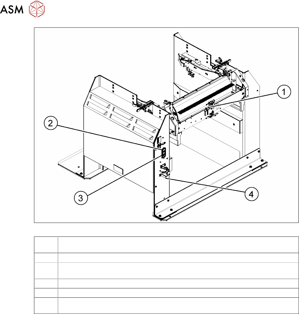
Fig.476: Docking station – back
1 Control valve [03003489-xx]
9.4.11
"Replacing the control valve" [}353]
2 ON/OFF switch
3 Microfuse [03033387-xx]
9.4.3
"Replacing the micro switch" [}340]
4 Pressure control valve for bulkcase feeder and main connection (5.5 bar)
9.4.6 "Replacing the positions end switch of the component trolley locking device" [}344]
9.4.9 "Replacing the Complete Coupling - Earthing and Compressed Air for the Bulk
Case" [}350]
9 Component feeding
9.4 Docking Station for Component Trolley
Service Manual SIPLACE X-Series S (from Hxxxx) 01/2021 339
9.4.2 Replacing the power pack
NOTICE
Observing the technical information
► Observe the technical information "Power pack for docking station for component trol-
ley SIPLACE X [116933] and SX [116965] has been discontinued" [DE:
TI2015-04D07] [EN: TI2015-04E07].
Parts
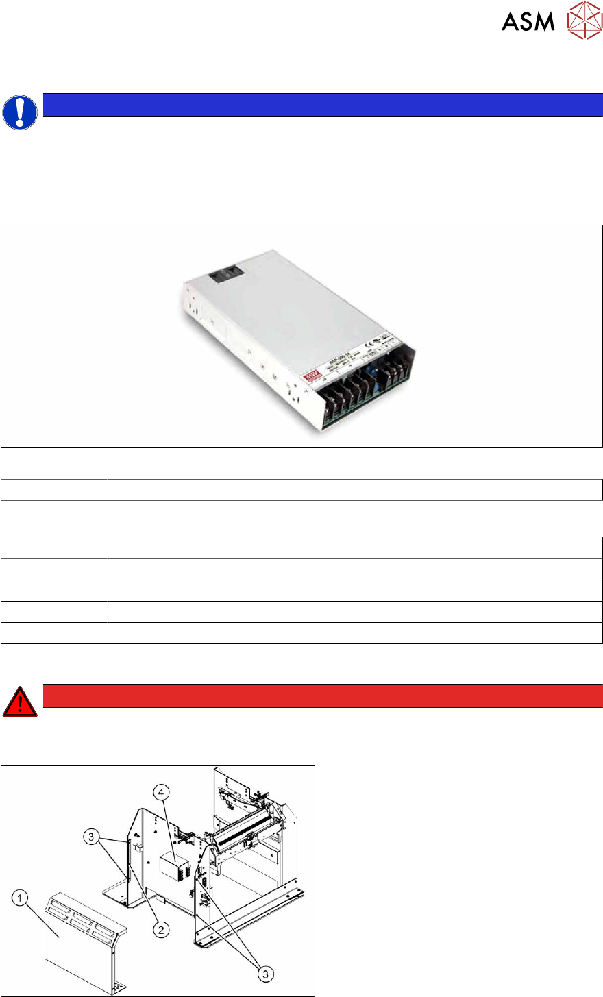
Fig.477: Switching power supply RSP-500-27 [03121806‑xx]
03121806‑xx Switching power supply RSP-500-27 (replaces: [03025938‑xx])
Equipment and tools
00353832-xx Allen key set
Wire cutters
Cable tie
Voltage measuring device
Circuit diagram folder for your machine
Removal/installation
DANGER
Switch off the voltage supply
► Press the ON/OFF button to switch off and disconnect the power supply.
Fig.478: Removing the cover
The power pack(4) is located behind the
cover(1)
.
► Remove the four screws(3) fastening
the cover. The cover is clamped in
place with the help of the bar(2)
.
► Pull the cover out of the docking sta-
tion.
Pay attention to the ground connection.
9 Component feeding
9.4 Docking Station for Component Trolley
340 Service Manual SIPLACE X-Series S (from Hxxxx) 01/2021
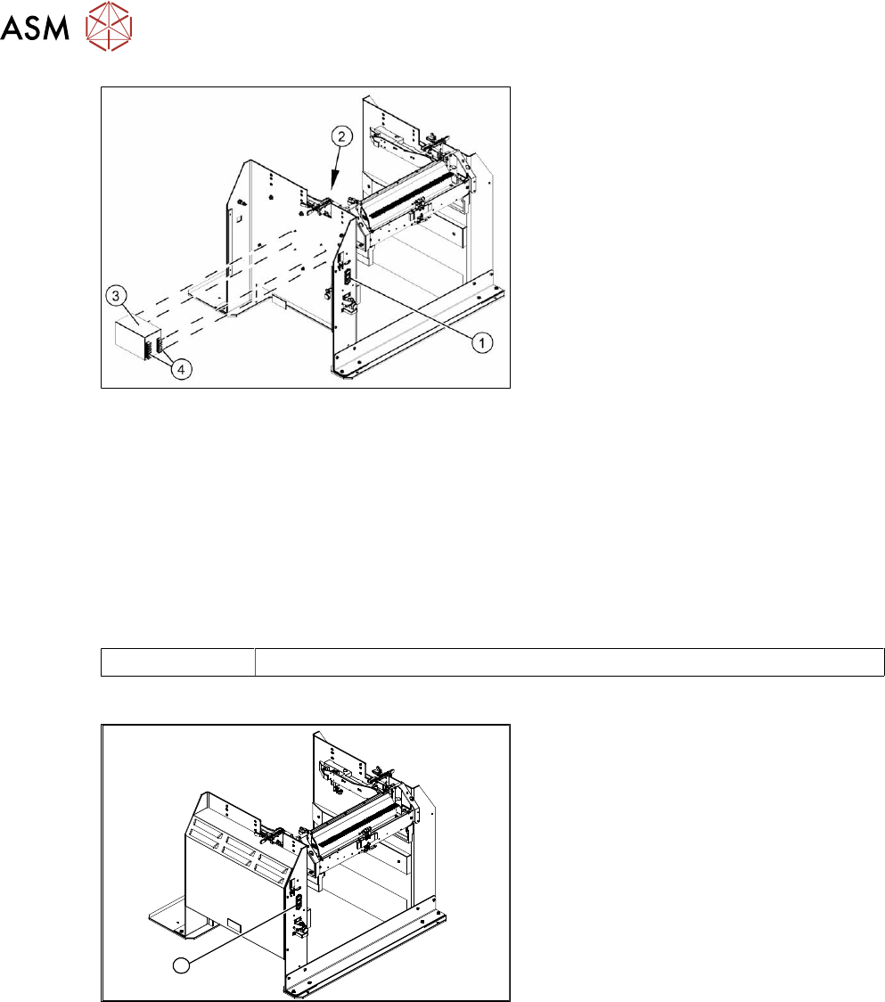
Fig.479: Removing the power pack
► Disconnect all electrical connections(4)
to the power pack(3). You may want to
mark their positions to make clear as-
signment easier later on.
► Remove the four screws(2) fastening
the power pack and then remove the
power pack.
► Connect all cables and fit the new
power pack.
► Press the ON/OFF button(1) to switch
on.
► Set the output voltage of the power pack at terminals nine and twelve:
– Standard (without BulkFeeder):
26.8 V (+/- 0.5 V)
– When using the BulkFeeders the output voltage is set permanently to 28.0V(+/‑0.5V).
► Refit the cover.
9.4.3 Replacing the micro switch
Parts
03033387‑xx Microfuse
Overview
1
Fig.480: Microfuse on docking station
1. Position of microfuse (T 8.0 A)