00198829-01_SM_X-Series-S_Hxxxx_EN.pdf - 第343页
9 Component feeding 9.4 Docking Station for Component Trolley Service Manual SIPLACE X-Series S (from Hxxxx) 01/2021 343 9.4.5 Replacing the locking lever Parts Fig.485: Horizontal tensioner 03025104-xx Horizontal tensi…
9 Component feeding
9.4 Docking Station for Component Trolley
342 Service Manual SIPLACE X-Series S (from Hxxxx) 01/2021
Overview
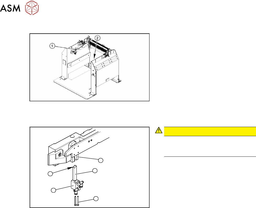
Fig.483: Locking unit left and right
1. Installation position of left locking unit
2. Installation position of right locking unit
Removal
5
1
4
3
2
Fig.484: Removing the locking unit
CAUTION!
Risk of injury
Risk of injury when disconnecting
pressurized compressed air lines.
.
► Switch off the compressed air supply.
► Remove the pneumatic connections on
the short-stroke cylinder.
► Remove the two screws (1) fastening
the short-stroke cylinder (2)
.
► Pull the short-stroke cylinder and the
locking slider(3)
downwards and out of
the guidance block(5)
.
► Unscrew the locking slider from the
short-stroke cylinder(2)
.
Installation
► Fit the locking slider onto the new short-stroke cylinder.
► Clean the locking sliders and the guidance block with a clean, lint-free cloth and lubricate both
slightly with Unisilikon.
► Move the locking slider into the guidance block, so that the beveled side (4) is pointing to the
front (in the direction of travel). This is important when moving the component trolley in.
► Fit the short-stroke cylinder with the two fastening screws.
► Reconnect to the compressed air supply.
► Switch the compressed air supply on and check that the left and right locking sliders move out
at the same time.
► If necessary, adjust the throttle valve on the short-stroke cylinder.
9 Component feeding
9.4 Docking Station for Component Trolley
Service Manual SIPLACE X-Series S (from Hxxxx) 01/2021 343
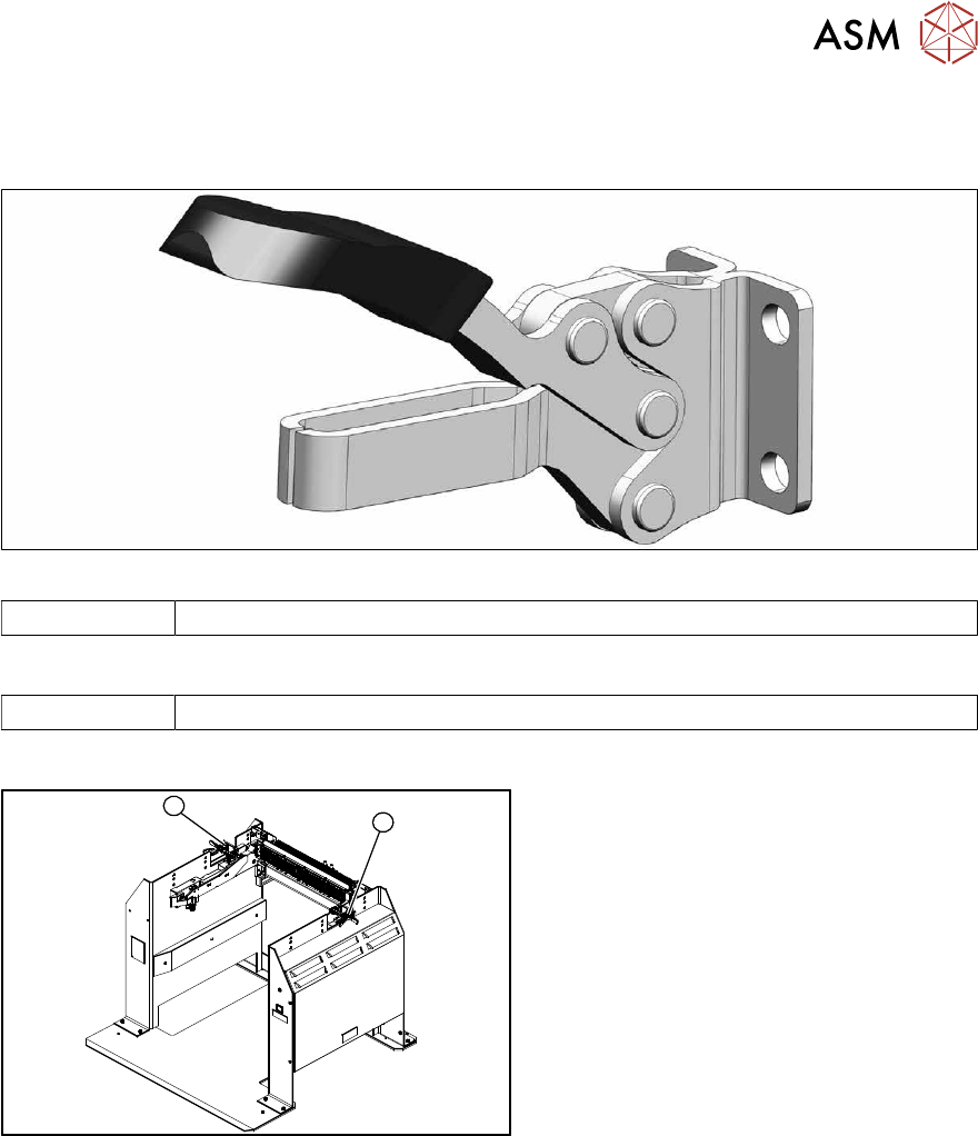
9.4.5 Replacing the locking lever
Parts
Fig.485: Horizontal tensioner
03025104-xx Horizontal tensioner DE-STA-CO 225-U
Equipment and tools
00353832-xx Allen key set
Overview
1
2
Fig.486: Locking lever left and right
1. Locking lever – on the left side
2. Locking lever – on the right side
9 Component feeding
9.4 Docking Station for Component Trolley
344 Service Manual SIPLACE X-Series S (from Hxxxx) 01/2021
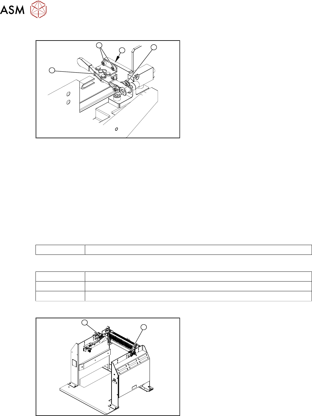
Removal
4
3
2
1
Fig.487: Removing the locking lever
1. Locking lever
2. Four fixing screws
3. Position end switch
4. Limit switch
► Remove the four screws(2) (twoeach
at the top and bottom) fastening the
locking lever(1)
.
► Remove the locking lever.
Installation
► Loosely screw in the new locking lever.
► Align the locking lever to the edge (3) and tighten the four fastening screws.
► Check that the limit switch (4) is actuated when the locking lever is closed. Correct the posi-
tion of the locking lever if necessary.
► Check the position end switch function by trying out the locking procedure.
9.4.6 Replacing the positions end switch of the component trolley locking device
Parts
03033395-xx Position end switch
Equipment and tools
00353832-xx Allen key set
Wire cutters
Cable ties
Overview
1
2
Fig.488: Position end switch left and right
1. Position end switch – on the left side
2. Position end switch – on the right side