00198829-01_SM_X-Series-S_Hxxxx_EN.pdf - 第360页
9 Component feeding 9.6 Smart Pin Support 360 Service Manual SIPLACE X-Series S (from Hxxxx) 01/2021 9.6.3 Replacing the back section of the cylinder CAUTION Do not change! The back section of the cylinder is preset with…
9 Component feeding
9.6 Smart Pin Support
Service Manual SIPLACE X-Series S (from Hxxxx) 01/2021 359
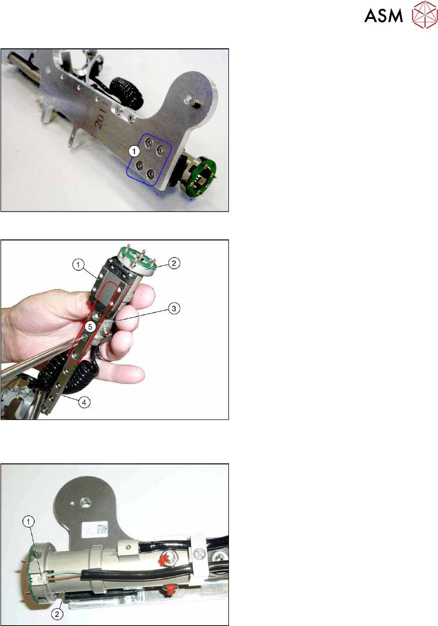
Fig.514: Screws fastening the linear guide
► Remove the fourscrews(1) fastening
the linear guide.
► Remove the linear guide from the base
plate. To do this, unhook the spring
from the top of the linear guide.
Fig.515: Screws fastening the cylinder
1. Trolley on the linear guide
2. Cylinder - front section
3. Cylinder - back section
4. Linear guide
5. Fastening screw for cylinder front and
back sections on the linear guide (par-
tially concealed by the trolley)
► Remove the screws fastening the front and back sections of the cylinder.
Fig.516: Connector
► Unplug the electrical connection(1) on
the front section of the cylinder(2)
.
► Remove the front section of the cylin-
der.
Installation
Follow the removal instructions in reverse order for installation. Observe the following note:
► When you screw in the linear guide trolley, press it to the left, against the stop edge, so that it
lies flush against the base plate.
9 Component feeding
9.6 Smart Pin Support
360 Service Manual SIPLACE X-Series S (from Hxxxx) 01/2021
9.6.3 Replacing the back section of the cylinder
CAUTION
Do not change!
The back section of the cylinder is preset with a cover strip take-up force of 12N+/‑2N for
the Pin Picker and may not be changed.
Parts, equipment and tools
●
Cylinder back section assembly [03089379Sxx]
●
Assembly instructions "Smart Pin Support" for SIPLACE X‑SeriesS [DEEN:00197394‑xx]
Overview
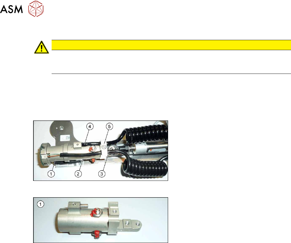
Fig.517: Cylinder
1. Cylinder - front section
2. Cylinder - back section
3. Swivel head
4. Pneumatic connection to the back sec-
tion of the cylinder
5. Strain relief
Fig.518: Cylinder - back section
1. Cylinder - back section
Removal
► Switch off the machine, disconnect it from the power supply and secure it to prevent
unauthorized reactivation.
1.2 "Preparatory work..." [}16]
► Remove the Pin Picker.
9.6.1 "Replacing the Pin Picker Assembly" [}357]
► Remove the front section of the cylinder. For more information, read section 9.6.2 "Replacing
the front section of the cylinder" [}358].
► Remove the screw fastening the strain relief.
► Unplug the pneumatic connection leading to the back section of the cylinder.
► If you have not already done so, remove the two screws fastening the back section of the cyl-
inder to the linear guide and then remove the back section of the cylinder.
Installation
Follow the removal instructions in reverse order for installation. Also observe the following instruc-
tions:
► When you screw in the linear guide trolley, press it to the left, against the stop edge, so that it
lies flush against the base plate.
► Make sure that the coil hose and the coiled cable do not touch when fully extended.
► Check that the sensors switch properly. The switch tag of the linear guide must have approx.
1 mm space to the trolley.
9 Component feeding
9.6 Smart Pin Support
Service Manual SIPLACE X-Series S (from Hxxxx) 01/2021 361
9.6.4 Replacing the linear guide
Parts, equipment and tools
●
SPS linear guide [03084323Sxx]
●
Assembly instructions "Smart Pin Support" for SIPLACE X‑SeriesS [DEEN:00197394‑xx]
Overview
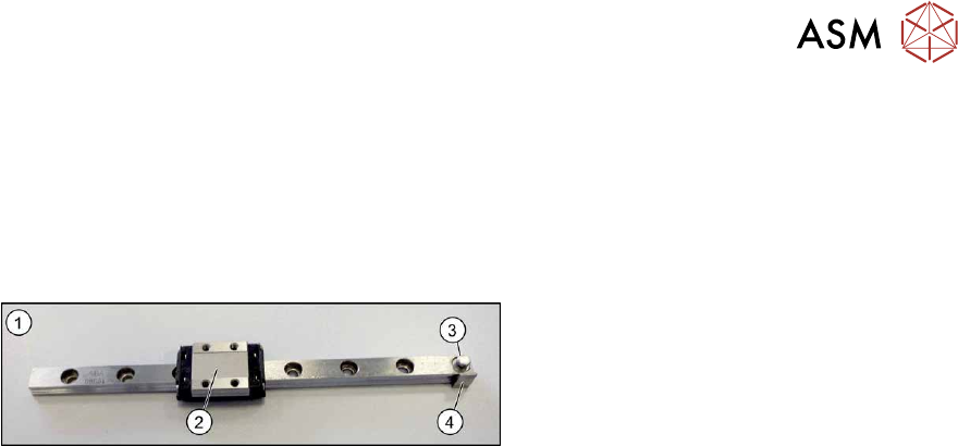
Fig.519: Linear guide
1. Linear guide
2. Trolley
3. Eyelet for hooking up the tension spring
4. Switch tag
Removal
► Switch off the machine, disconnect it from the power supply and secure it to prevent
unauthorized reactivation.
1.2 "Preparatory work..." [}16]
► Remove the Pin Picker.
9.6.1 "Replacing the Pin Picker Assembly" [}357]
► Remove the front section of the cylinder. For more information, read section 9.6.2 "Replacing
the front section of the cylinder" [}358].
► Remove the back section of the cylinder. For more information, read section 9.6.3 "Replacing
the back section of the cylinder" [}360].
► Remove the linear guide.
Installation
Follow the removal instructions in reverse order for installation. Also observe the following instruc-
tions:
► When you screw in the linear guide trolley, press it to the left, against the stop edge, so that it
lies flush against the base plate.
► Check the linear guide travel path. The linear guide must be easy to move along the whole
length.
► Check that the sensors switch properly.
The switch tag of the linear guide must have between 0.7 and 1.4 mm space to the sensor
above or below.
The top sensor must switch after 2mm when travelling downwards.