00198829-01_SM_X-Series-S_Hxxxx_EN.pdf - 第45页
3 Power supply 3.1 Electrical System Service Manual SIPLACE X-Series S (from Hxxxx) 01/2021 45 3 Power supply DANGER Observe User Manual ► Please observe the safety instructions in the user manual for all work! 3.1 Elect…
2 Basic Machine
2.8 Nozzle Changers and Reject Boxes
44 Service Manual SIPLACE X-Series S (from Hxxxx) 01/2021
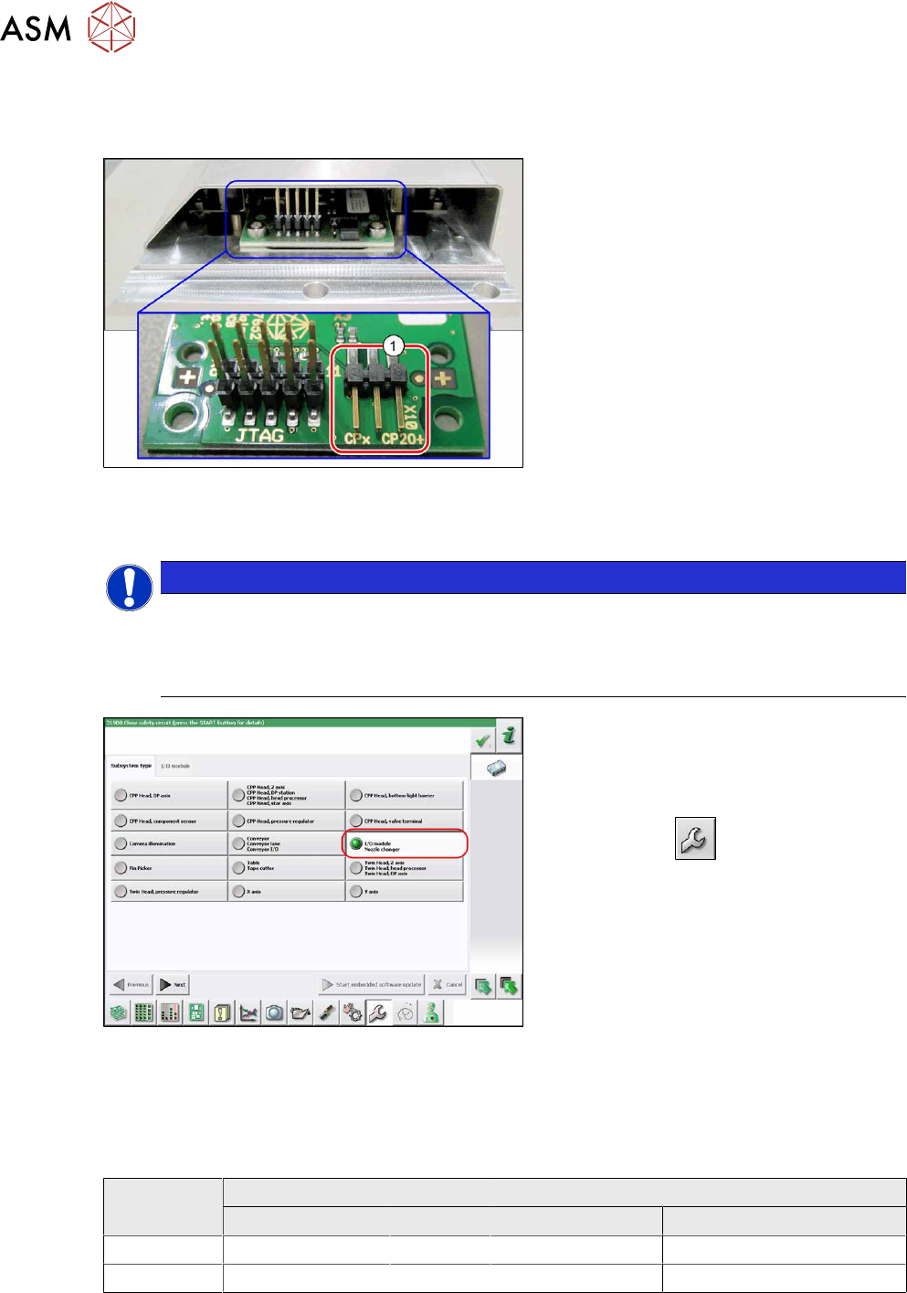
2.8.6 Jumpers on the Nozzle Changer
Overview
Fig.40: Jumpers on the nozzle changer
1. Jumper X10
The jumper X10 needs to be set at the fol-
lowing nozzle changers:
●
Nozzle changer basic structure
CPx - short assembly [03147925‑xx]
(replaces [03103649‑xx],
[03062463‑xx])
●
Nozzle changer basic structure
CPx – long assembly [03147324-xx]
●
Nozzle changer basic structure
CPx – long assembly [03103514-xx]
Preparation
NOTICE
Before installation
Due to the design, this setting must be performed before installation in the machine.
► If the new nozzle changer is being fitted as a spare part in a machine with I/O module
control, you will need to reconnect the jumper to pin 1-2.
Fig.41: Checking the I/A module control
To check whether the machine has I/O mod-
ule control, proceed as follows:
► Switch over to the operator level Ser-
vice.
► Click on the button.
► Click on the Embedded software but-
ton.
► Click the Update subsystem button.
► If an I/O module control is present, you
will see the entry Nozzle Changer
at I/
O Module.
Adjustment
► Set the correct value on the jumper for your head type, software and control method.
Jumper X10
Head SW <= 706.x SW >= 707.x
I/O controller XFCU I/O controller XFCU
CPx, DLM 1-2 1-2 1-2 2-3
C&P20P --- --- --- 2-3 (factory settings)
3 Power supply
3.1 Electrical System
Service Manual SIPLACE X-Series S (from Hxxxx) 01/2021 45
3 Power supply
DANGER
Observe User Manual
► Please observe the safety instructions in the user manual for all work!
3.1 Electrical System
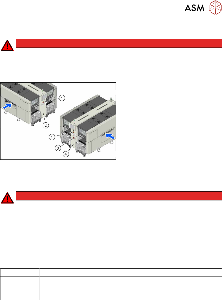
Fig.42: Electrics (example of X4i S shown)
1. Emergency stop button
2. MHCU, MGCU, BoxPC
(behind the cover)
3. Main switch
4. Power supply (behind the cover)
3.2 Electrical Checks
DANGER
Observe the safety instructions
There is a risk of dangerous touch voltages and short circuits occurring in power supplies
which have been made accessible and are connected for measurement purposes.
Nonobservance of these safety instructions may cause injury to personnel and dam-
age to the machine!
Measurements may only be performed by specially trained service technicians with appro-
priate qualifications and expertise.
► Observe the safety instructions in this manual and in the instruction manual.
Equipment and tools
00096290-xx Fork wrench set
DUSPOL voltage tester
Digital voltmeter, class 1,5
Test cable with test probes or terminals
3 Power supply
3.2 Electrical Checks
46 Service Manual SIPLACE X-Series S (from Hxxxx) 01/2021
Preparation
CAUTION
Take care not to damage the supply lines!
Make sure that the main power cable and supply cables in the machine are not trapped and
that the insulation is not damaged.
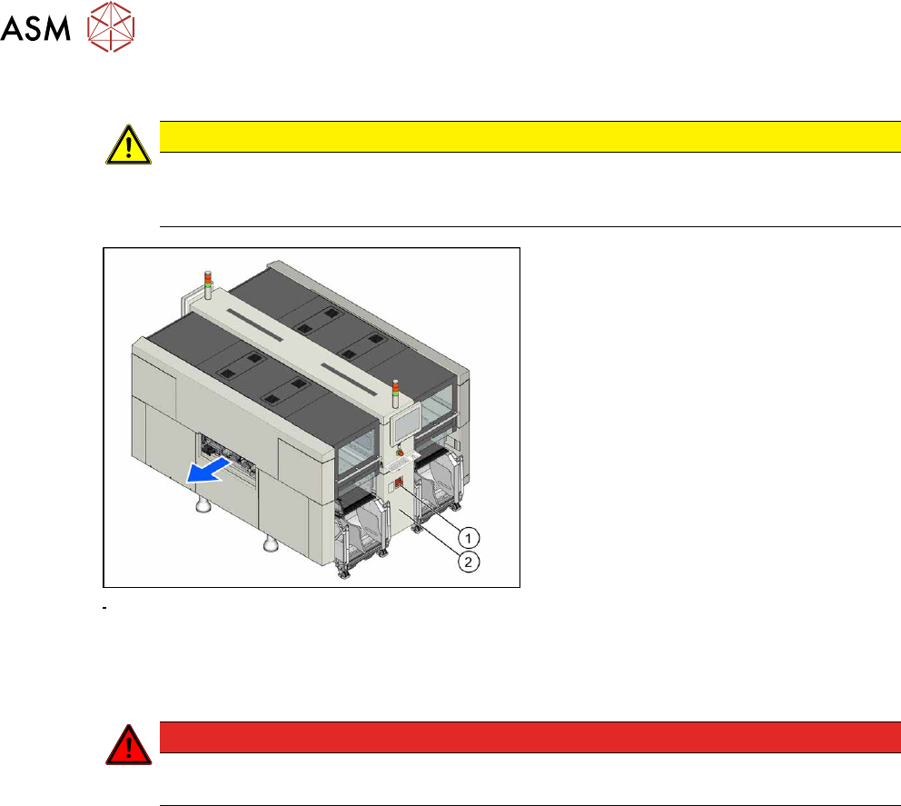
Fig.43: Main switch
► End all placement operations and
switch the machine off at the main
switch(1)
.
► Disconnect the machine from the main
power supply.
► Open the lock on the power supply
cover(2)
.
► Remove the power supply fastening screw and pull out the power supply.
► Reconnect the machine to the power supply.
DANGER
Touch voltages
Careful: there may be dangerous touch voltages in the vicinity of the open power supply!
► Switch the machine on again at the main switch and start it up.
Voltages
► Measure the required voltages.
Please refer to the relevant circuit diagram for your machine for details of the various voltages.
●
Detailed circuit diagrams folder for SIPLACE X-Series S (from Hxxxx) [DE+EN:00197920‑03]
●
Detailed circuit diagrams folder for SIPLACE X-Series S (from H1440) [DE EN: 00197920-04]
●
Detailed circuit diagrams folder for SIPLACE X-Series S (from H2500) [DE EN: 00198730-xx]