00198829-01_SM_X-Series-S_Hxxxx_EN.pdf - 第48页
3 Power supply 3.4 Power supply and transformer modules 48 Service Manual SIPLACE X-Series S (from Hxxxx) 01/2021 3.4 Power supply and transformer modules DANGER Checking for absence of voltage! ► Before you start workin…
3 Power supply
3.3 Pulling out the Power Supply
Service Manual SIPLACE X-Series S (from Hxxxx) 01/2021 47
3.3 Pulling out the Power Supply
CAUTION
Risk of tipping
If you pull out the power supply completely, there is a risk of tipping.
► Support the power supply from below.
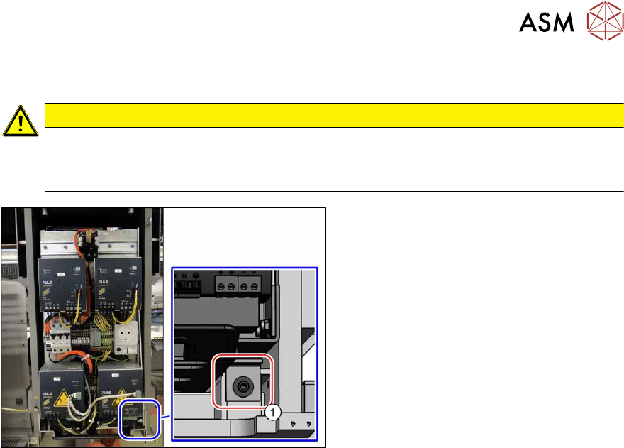
Fig.44: Screw fastening the power supply
For some service tasks it is necessary to pull
the power supply out of the machine.
► Remove the screw (1) fastening the
power supply.
► Pull the power supply out as far as ne-
cessary.
3 Power supply
3.4 Power supply and transformer modules
48 Service Manual SIPLACE X-Series S (from Hxxxx) 01/2021
3.4 Power supply and transformer modules
DANGER
Checking for absence of voltage!
► Before you start working, check the power supply for absence of voltage and observe
the waiting times!
See also
2 3.4.3 "Checking For Absence of Voltage" [}49]
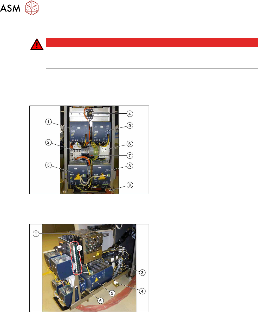
3.4.1 Overview
Fig.45: Overview of the power supply front
1. AC/DC-Converter DC24V/40A 3-
PHASE [03102840‑xx]
2. Circuit breaker FAZ-C16/3-NA 16A 3p
[03118366‑xx]
3. AC/DC converter DC300/150V 1.3kW 3
phase [03103087‑xx]
4. Main switch [03114066-xx]
5. AC-/DC converter 36V 26.7A 960W 3
phase [03103331‑xx]
6. Service socket (if present)
7. Measuring points for absence of
voltage
2x 300 V DC and ground
8. AC/DC converter DC300/150V 1.3kW 3
phase [03103087‑xx]
9. Locking screw for power supply
Fig.46: Overview of the power supply at the side
1. Contactor safety breaker [03112066‑xx]
2. Distribution and fusing assembly X-
SeriesS [03118289‑xx]
3. Connections for vacuum pump
4. Connection for 110 Volt option
5. Capacitor battery PCS417.771
[03106016‑xx]
6. AC/DC-Converter DC24V/20A 3-
PHASE [03055232‑xx]
3.4.2 Electrical and Control Settings
For more detailed information refer to the circuit diagrams folder of your machine.
●
Detailed circuit diagrams folder for SIPLACE X-Series S (from Hxxxx) [DE+EN:00197920‑03]
●
Detailed circuit diagrams folder for SIPLACE X-Series S (from H1440) [DE EN: 00197920-04]
●
Detailed circuit diagrams folder for SIPLACE X-Series S (from H2500) [DE EN: 00198730-xx]

3 Power supply
3.4 Power supply and transformer modules
Service Manual SIPLACE X-Series S (from Hxxxx) 01/2021 49
3.4.3 Checking For Absence of Voltage
DANGER
Power supply
The assembly contains energy-storing components (CAP and capacitors on the FDB
assembly)!
After switching off at the main switch or disconnecting from the main supply, hazardous
voltages are still present at some points of the assembly interior for a period of approx. five
minutes.
► Before performing any service work or disconnecting press-fit connections, make sure
that you check for absence of voltage - as described further below! Maintenance or re-
placement may only be performed when the assembly is de-energized.
► All press-fit connections for the CAP assembly and PS1 are of touch-proof design but
when connections are plugged in or unplugged while there is still residual voltage
(CAP capacitors are still charged, display lamps on PS1 or CAP still shine), this could
cause damage or destruction of these or other connected components!
Protective measures and rules of conduct
Tools / requirements:
●
The certified electrician or person instructed and trained in electrical matters must be familiar
with the voltage tester and with the particular details of the system (defined contact points for
determining absence of voltage).
●
Use certified voltage testers and phase testers with a certain fixed measuring range.
The use of universal and multiple measuring devices for determining the absence of voltages
is not permitted.
Only use two-pin voltage testers (DUSPOL) e.g. FLUKE T150 or T5-1000.
●
Knowledge of the user guide and all safety instructions specified by the voltage tester manu-
facturer is a requirement.
●
Observe the area of use for the measuring device (nominal voltage, protection class, voltage
type, switch-on period, temperature range, measurement category CAT IV
).
●
Check the external energy source of the measuring device.
●
Wear closely fitting and closed workwear.
●
Technicians working alone must be able to take any occurring risks into consideration and to
master them. In the event of any confusion, consult your specialist superior.
Preparation:
●
Use the voltage testers in accordance with their intended use. Inspect them for damage prior
to use. Damaged devices or cables may not be used and are to be reported immediately.
●
Before performing any measurements, test the voltage testers for functionality on a comparat-
ive voltage source or perform an integrated function test.
●
Ensure safe handling/safe workplace. Take sufficient space for movement and lighting into ac-
count.
●
Secure the area against proximity and hazard from persons.
●
Pay attention to any nearby exposed or active parts. Secure the measurement area, if neces-
sary.