00198829-01_SM_X-Series-S_Hxxxx_EN.pdf - 第64页
3 Power supply 3.4 Power supply and transformer modules 64 Service Manual SIPLACE X-Series S (from Hxxxx) 01/2021 3.4.11.1 Distribution and fusing board assembly Fig.71: Distribution and fusing board assembly [03118289‑…
3 Power supply
3.4 Power supply and transformer modules
Service Manual SIPLACE X-Series S (from Hxxxx) 01/2021 63
3.4.11 Replacing the Distribution and Fusing Assembly
Parts, equipment and tools
●
Distribution and fusing board assembly [03118289‑xx]
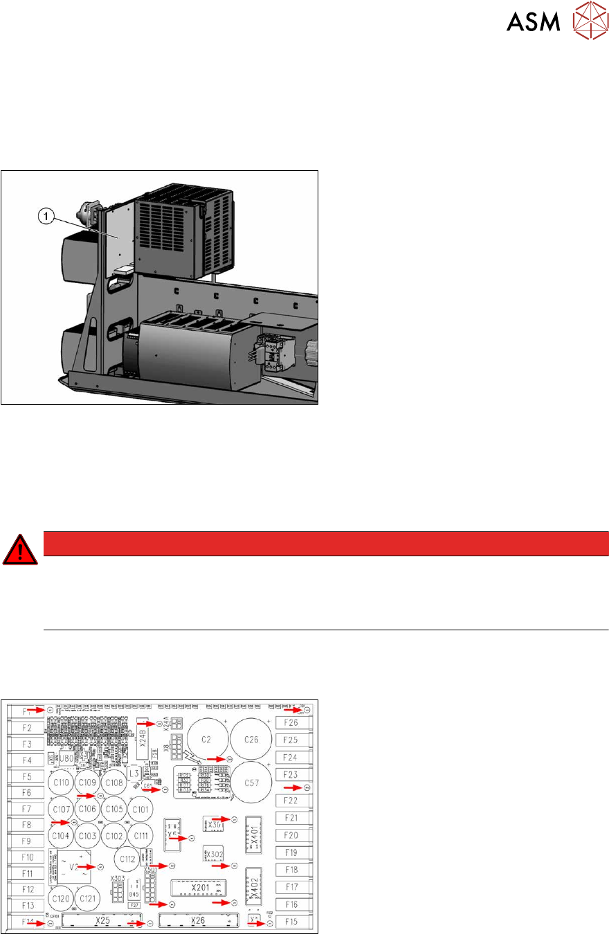
Overview
Fig.69: Distribution and fusing board assembly
1. Distribution and fusing board assembly
Removal
► Switch off the machine, disconnect it from the power supply and secure it to prevent
unauthorized reactivation.
1.2 "Preparatory work..." [}16]
DANGER
Checking for absence of voltage!
► Before you start working check the power supply for absence of voltage and observe
the waiting times! For more information about this read section 3.4.3
"Checking For
Absence of Voltage" [}49].
► Unplug all electrical connections to the board. You may like to mark their positions, to make
clear assignment easier later on.
3.4.11.1 "Distribution and fusing board assembly" [}64]
Fig.70: Fastening screws
► Remove the fastening screws on the
board and the ground conductor.
► Remove the board.
Installation
Follow the removal instructions in reverse order for installation.
3 Power supply
3.4 Power supply and transformer modules
64 Service Manual SIPLACE X-Series S (from Hxxxx) 01/2021
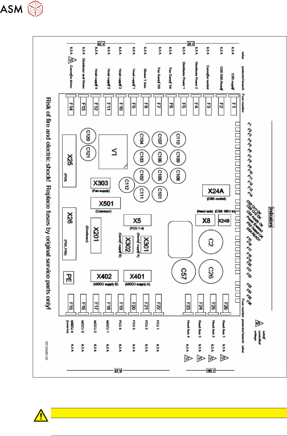
3.4.11.1 Distribution and fusing board assembly
Fig.71: Distribution and fusing board assembly [03118289‑xx]
●
Micro fuse 5x20mmT 6.3A 250V (spare part) [03078843‑xx]
Each machine is supplied with a pack of 10 fuses.
CAUTION
Use only 6.3A fuses!
► If 10A fuses are present, replace them by 6.3A fuses.
4 Electrics and control system
4.1 Electrical System
Service Manual SIPLACE X-Series S (from Hxxxx) 01/2021 65
4 Electrics and control system
DANGER
Observe User Manual
► Please observe the safety instructions in the user manual for all work!
4.1 Electrical System
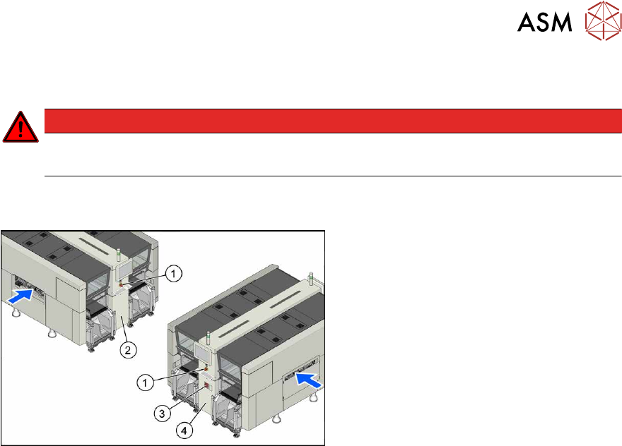
Fig.72: Electrics (example of X4i S shown)
1. Emergency stop button
2. MHCU, MGCU, BoxPC
(behind the cover)
3. Main switch
4. Power supply (behind the cover)