00198829-01_SM_X-Series-S_Hxxxx_EN.pdf - 第70页
4 Electrics and control system 4.2 BoxPC 70 Service Manual SIPLACE X-Series S (from Hxxxx) 01/2021 4.2.4 Replacing the RAM in the BoxPC Parts, equipment and tools NOTICE RAM Microsoft Windows 10 needs 4 GB RAM. PC type R…
4 Electrics and control system
4.2 BoxPC
Service Manual SIPLACE X-Series S (from Hxxxx) 01/2021 69
4.2.3 Replacing the LAN card
Parts, equipment and tools
●
LAN card PCI-Express 2x gigabit LAN [03198999‑xx] (replaces [03118416‑xx])
Overview
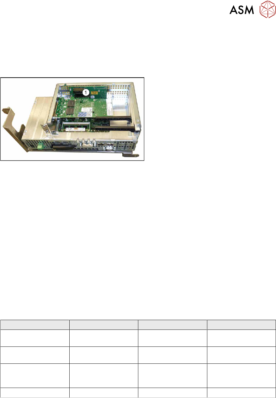
Fig.76: BoxPC 427D
1. Free slot for the LAN card
The "LAN card PCI-Express 2x gigabit
LAN" [03118416-xx] is required for the in-
stalled 3D coplan or barcode scanner.
Removal
The plug-in card is fitted in the BoxPC.
► Switch off the machine, disconnect it from the power supply and secure it to prevent
unauthorized reactivation.
1.2 "Preparatory work..." [}16]
► Dismantle and remove the BoxPC from the machine.
► Open the covers above the plug-in cards.
► Remove the screw fastening the LAN card and remove the LAN card.
Installation
Follow the removal instructions in reverse order for installation. Also observe the following instruc-
tions:
► Make sure that the plug-in card is correctly fitted into its slot.
► Configure the IP settings for the LAN card (see below):
Overview of IP addresses
IP address Subnet mask Comment
SIPLACE Lan 172.22.xxx.xxx 255.255.0.0 LAN connection on the
computer
CIN-Box 192.168.255.239 255.255.255.224 LAN connection on the
computer
Station computer 192.168.255.249 255.255.255.240 Additional LAN card for
the coplanarity com-
puter
Coplanarity computer 192.168.255.253 255.255.255.240
4 Electrics and control system
4.2 BoxPC
70 Service Manual SIPLACE X-Series S (from Hxxxx) 01/2021
4.2.4 Replacing the RAM in the BoxPC
Parts, equipment and tools
NOTICE
RAM
Microsoft Windows 10 needs 4 GB RAM.
PC type RAM module type
BoxPC 427D [03114177Sxx] 4 GB DDR 1333Mhz PC3-10600 SO-DIMM
For coplan:
BoxPC ABP402-A CPU1020E 2xPCI SSD
(iBase) [03120423‑xx]
(replaces: BoxPC 627C [03094731‑xx])
2x 2GB DDR3 SO-DIMM
For more information about the memory modules and sizes needed, refer to the parts catalogue
or contact the SIPLACE hotline.
Overview
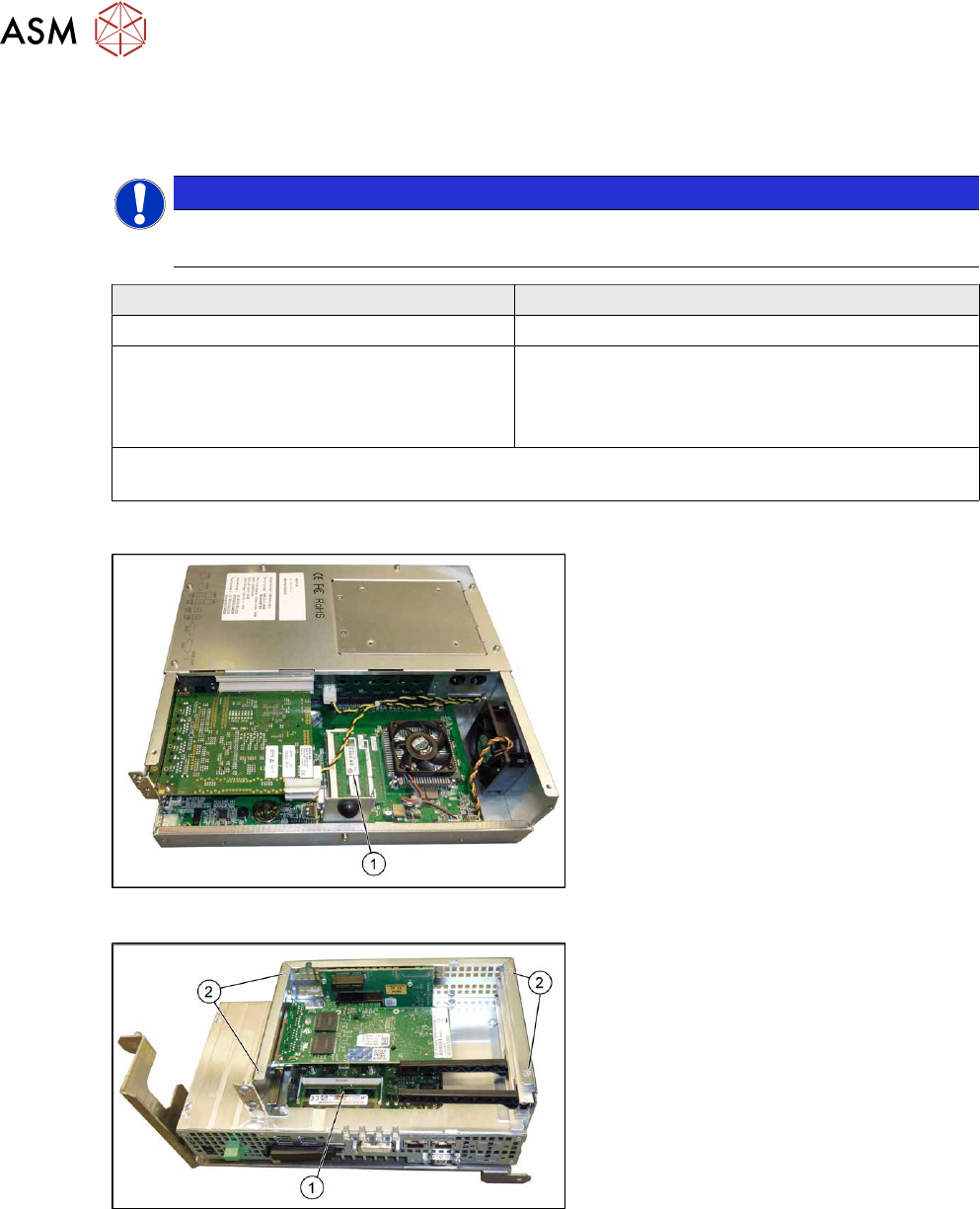
Fig.77: BoxPC ABP402-A iBase
1. Memory extension
Fig.78: BoxPC 427D
1. Memory extension
2. Four screws fastening the cover
Removal
► Switch off the machine, disconnect it from the power supply and secure it to prevent
unauthorized reactivation.
1.2 "Preparatory work..." [}16]
► Dismantle and remove the BoxPC from the machine.
► Remove the screws fastening the cover of the BoxPC and open the cover.
► If needed, remove the plug-in cards blocking access to the memory extension.
► Open the locks on both sides of the memory extension and remove the memory extension.
4 Electrics and control system
4.3 Replacing the cover fan
Service Manual SIPLACE X-Series S (from Hxxxx) 01/2021 71
Installation
Follow the removal instructions in reverse order for installation. Also observe the following instruc-
tions:
► Make sure that you insert the memory extension the right way round. The new memory exten-
sion must audibly engage into its slot.
4.3 Replacing the cover fan
Parts, equipment and tools
●
Fan cover 1-part [03052317‑xx] (replaces: [03091773-xx])
●
Sealing varnish Loctite 241 [02101037-xx]
Overview
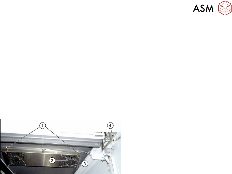
Fig.79: Overview of cover fan
1. Screws for fastening the cover plate
2. Cover fan
3. Fastening screws for cover fan
4. Connection cable for cover fan
Removal
► Switch off the machine, disconnect it from the power supply and secure it to prevent
unauthorized reactivation.
1.2 "Preparatory work..." [}16]
The fans are fastened to the cover plate, inside. First dismantle the cover plate:
► Unplug the connection cable(4).
► Remove the six screws (1) fastening the cover plate and remove the cover plate. Make sure
that the various washers are not lost. You may want to mark their positions, to make clear as-
signment easier later on.
► Remove the four screws (3) fastening the cover fan. Make sure that the washers are not lost.
► Unplug the cover fan connection cable and remove the cover fan from the machine.
Installation
Follow the removal instructions in reverse order for installation. Also observe the following instruc-
tions:
► When fitting the fan, note the correct direction of air flow. The fan must blow the air into the
machine. If necessary, you can use the adjacent fan as a guide. The flow of air is shown by
an arrow on the side of the fan housing.
► Secure the six screws fastening the cover plate with Loctite 241.