00198829-01_SM_X-Series-S_Hxxxx_EN.pdf - 第72页
4 Electrics and control system 4.4 Replacing the cover switch 72 Service Manual SIPLACE X-Series S (from Hxxxx) 01/2021 4.4 Replacing the cover switch Parts, equipment and tools ● Safety switch AZ 16-03zvrk-M16 3Oe [0305…
4 Electrics and control system
4.3 Replacing the cover fan
Service Manual SIPLACE X-Series S (from Hxxxx) 01/2021 71
Installation
Follow the removal instructions in reverse order for installation. Also observe the following instruc-
tions:
► Make sure that you insert the memory extension the right way round. The new memory exten-
sion must audibly engage into its slot.
4.3 Replacing the cover fan
Parts, equipment and tools
●
Fan cover 1-part [03052317‑xx] (replaces: [03091773-xx])
●
Sealing varnish Loctite 241 [02101037-xx]
Overview
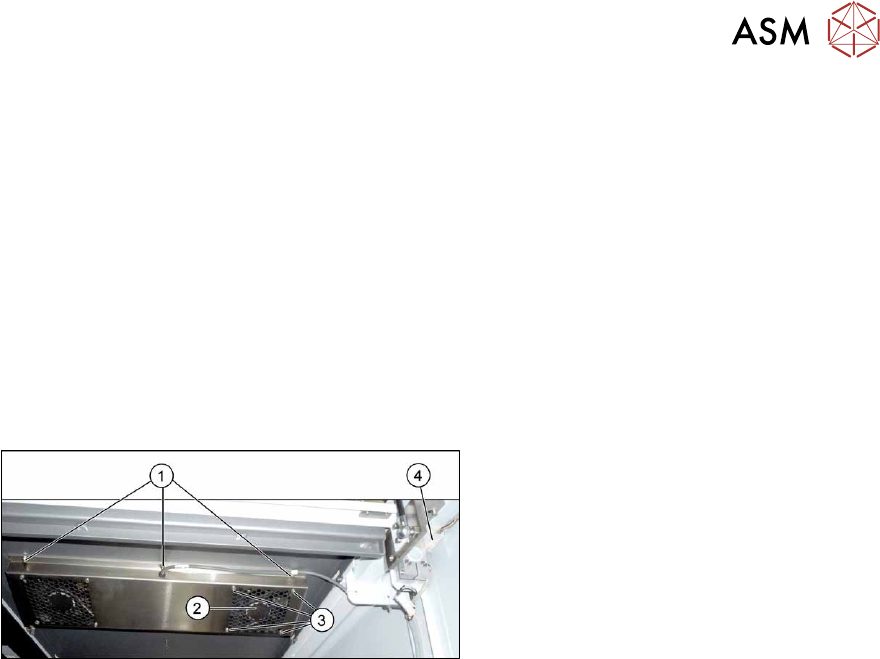
Fig.79: Overview of cover fan
1. Screws for fastening the cover plate
2. Cover fan
3. Fastening screws for cover fan
4. Connection cable for cover fan
Removal
► Switch off the machine, disconnect it from the power supply and secure it to prevent
unauthorized reactivation.
1.2 "Preparatory work..." [}16]
The fans are fastened to the cover plate, inside. First dismantle the cover plate:
► Unplug the connection cable(4).
► Remove the six screws (1) fastening the cover plate and remove the cover plate. Make sure
that the various washers are not lost. You may want to mark their positions, to make clear as-
signment easier later on.
► Remove the four screws (3) fastening the cover fan. Make sure that the washers are not lost.
► Unplug the cover fan connection cable and remove the cover fan from the machine.
Installation
Follow the removal instructions in reverse order for installation. Also observe the following instruc-
tions:
► When fitting the fan, note the correct direction of air flow. The fan must blow the air into the
machine. If necessary, you can use the adjacent fan as a guide. The flow of air is shown by
an arrow on the side of the fan housing.
► Secure the six screws fastening the cover plate with Loctite 241.
4 Electrics and control system
4.4 Replacing the cover switch
72 Service Manual SIPLACE X-Series S (from Hxxxx) 01/2021
4.4 Replacing the cover switch
Parts, equipment and tools
●
Safety switch AZ 16-03zvrk-M16 3Oe [03055263-xx]
Overview
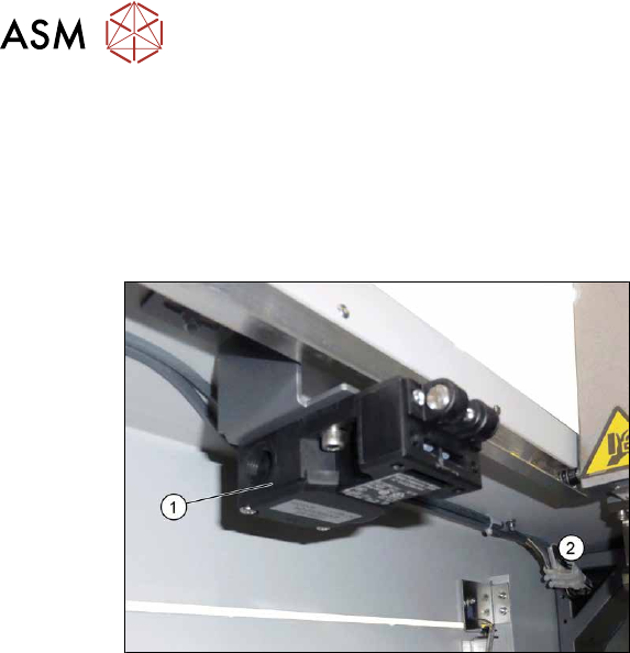
Fig.80: Cover switch
1. Cover switch
2. Connector
Removal
► Switch off the machine, disconnect it from the power supply and secure it to prevent
unauthorized reactivation.
1.2 "Preparatory work..." [}16]
► Unplug the connection cable from the cover switch.
► Remove the screws fastening the cover switch and remove the cover switch.
Installation
Follow the removal instructions in reverse order for installation. Also observe the following instruc-
tions:
► The cover switch must be set to the cover. Make sure that the cover switch is clean and
switches properly. The cover switch needs to be set so that even a minimal opening of the
cover will trigger the safety circuit.
Also read section 2.4
"Setting the Covers" [}27].
► Switch the machine on and make sure that the cover switch activates the safety circuit, when
the protective covers are opened.
4 Electrics and control system
4.5 Indicator lamp
Service Manual SIPLACE X-Series S (from Hxxxx) 01/2021 73
4.5 Indicator lamp
4.5.1 Replacing the indicator lamp/module
Parts
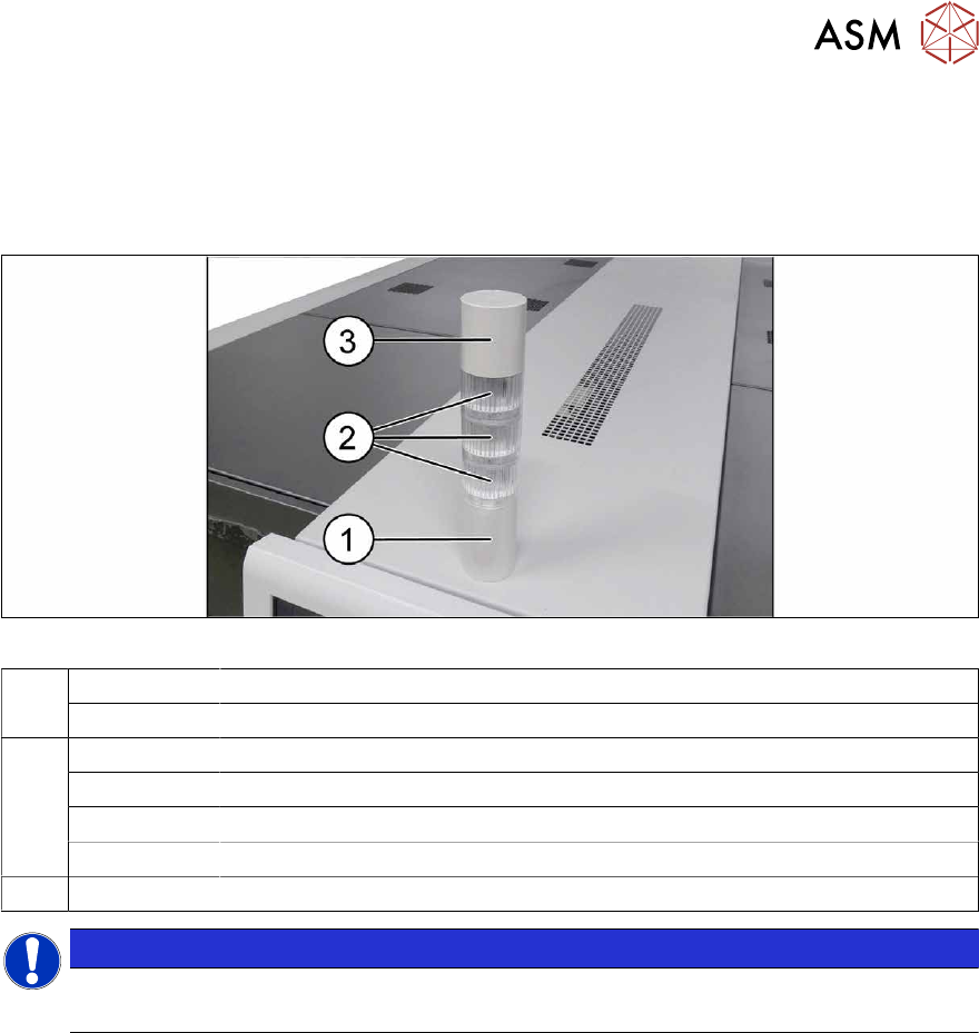
Fig.81: Indicator lamp
1 03162662-xx Basic module
03103211-xx Connecting cable
2 03162664-xx LED module LR5-E-RZ 50mm red, transparent
03162665-xx LED module LR5-E-YZ 50mm yellow, transparent
03162663-xx LED module LR5-E-GZ 50mm green, transparent
03162666-xx LED module LR5-E-CZ 50mm white, transparent
3 03162667‑xx Buzzer module LR5-BW 50mm
NOTICE
Do not separate the LED and its housing
The LED and the transparent housing can not be separated from one another.