00198829-01_SM_X-Series-S_Hxxxx_EN.pdf - 第78页
4 Electrics and control system 4.8 Replacing the CAN interface CINX 78 Service Manual SIPLACE X-Series S (from Hxxxx) 01/2021 4.8 Replacing the CAN interface CINX Parts, equipment and tools Fig.88: CAN interface CINX 1.…
4 Electrics and control system
4.7 Replacing the button
Service Manual SIPLACE X-Series S (from Hxxxx) 01/2021 77
4.7 Replacing the button
Parts, equipment and tools
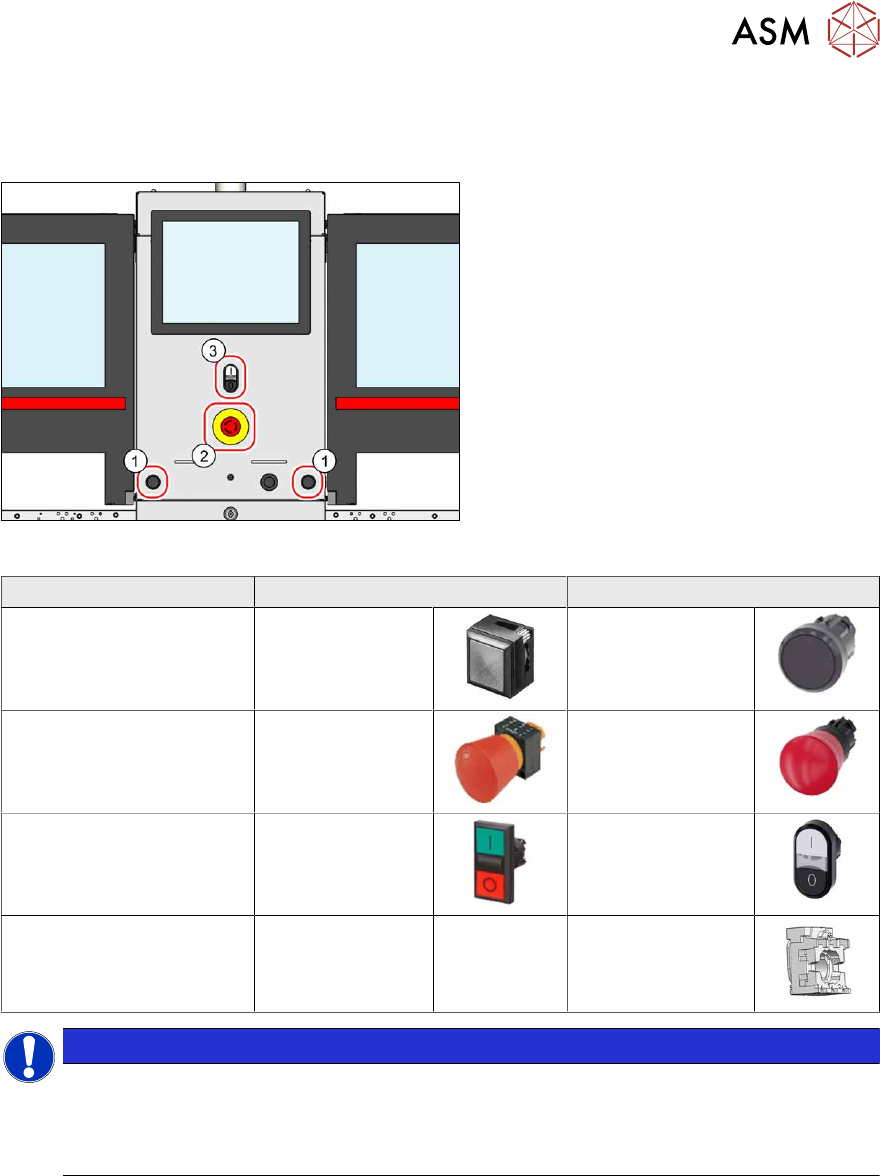
Fig.87: Overview of button
1. Pushbutton
2. Emergency stop button
3. Twin pushbutton
Square shape Round shape
Pushbutton 00334095‑xx 03164001Sxx
Emergency stop button 00334073‑xx 03165966Sxx
Twin pushbutton 03084513‑xx 03170336Sxx
Holder (for back of button
with round design)
--- 03164008‑xx
NOTICE
Square and round designs are not compatible with one another
The two designs are not compatible with one another and can not be exchanged with one
another.
► Always replace a button with one of the same design.
Removal
► Switch off the machine, disconnect it from the power supply and secure it to prevent
unauthorized reactivation.
1.2 "Preparatory work..." [}16]
► Remove the relevant button. To do this, unplug all electrical connections. You may like to
mark their positions, to make clear assignment easier later on.
Installation
Follow the removal instructions in reverse order for installation.
4 Electrics and control system
4.8 Replacing the CAN interface CINX
78 Service Manual SIPLACE X-Series S (from Hxxxx) 01/2021
4.8 Replacing the CAN interface CINX
Parts, equipment and tools
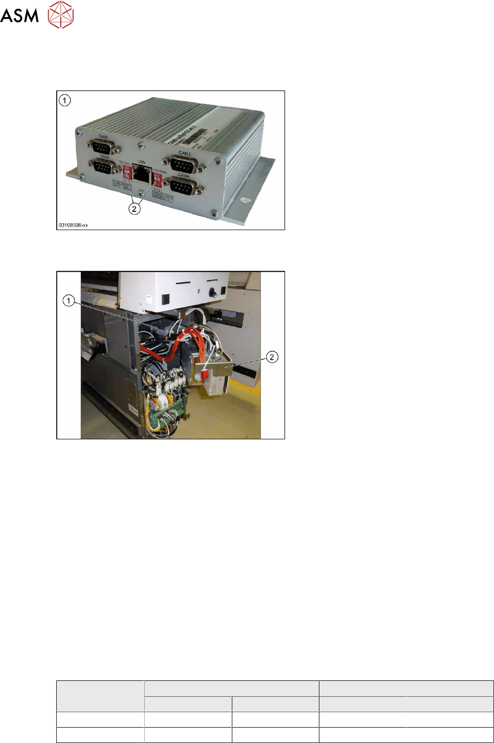
Fig.88: CAN interface CINX
1. CAN interface CINX [03108598-xx]
2. DIP switches
Overview
Fig.89: CAN interface in the machine
The CAN interface(1) is located between
location 1 and 2, behind the BoxPC(2)
.
The CAN interface is fixed with Velcro to the
machine base.
The CAN interface also features four con-
nections for diagnostics.
Removal
► Switch off the machine, disconnect it from the power supply and secure it to prevent
unauthorized reactivation.
1.2 "Preparatory work..." [}16]
► Lift off the keyboard (if present).
► Dismantle the lower cover between locations 1 and 2.
► Lift the BoxPC slightly and swing it forwards.
► Unplug all electrical connections to the CAN interface. Mark their positions, to make clear as-
signment easier later on.
► Take the CAN interface out of the machine.
Installation
Follow the removal instructions in reverse order for installation. Also observe the following note:
► Set the DIP switches. (see below).
DIP switch
Machine type DIP switch left DIP switch right
1 2 1 2
X-Series S ON ON ON ON
SX1/SX2 OFF OFF OFF OFF
4 Electrics and control system
4.9 Replacing the I/O control unit
Service Manual SIPLACE X-Series S (from Hxxxx) 01/2021 79
Connector
Connector Description
CAN 1 Gantry 1
CAN 2 Gantry 2
CAN 3 Gantry 3
CAN 4 Gantry 4
4.9 Replacing the I/O control unit
Parts, equipment and tools
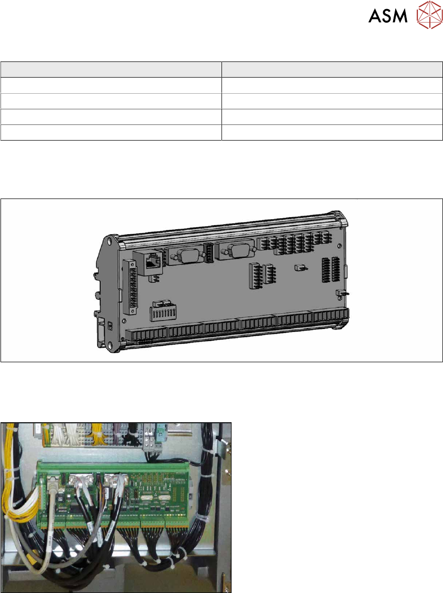
Fig.90: I/O control unit II [03116049-xx]
●
I/O control unit II [03116049-xx]
Overview
Fig.91: I/O control unit
The I/O control unit is located between loca-
tion 1 and 2, behind the bottom cover.
Removal
► Take a note of the component counter reading at the software user interface.
► Switch off the machine, disconnect it from the power supply and secure it to prevent
unauthorized reactivation.
1.2 "Preparatory work..." [}16]
► Unplug all press-fit connections. You might like to mark their positions to make clear assign-
ment easier later on.
► Pull the I/O control unit out of its mount.