00198829-01_SM_X-Series-S_Hxxxx_EN.pdf - 第79页
4 Electrics and control system 4.9 Replacing the I/O control unit Service Manual SIPLACE X-Series S (from Hxxxx) 01/2021 79 Connector Connector Description CAN 1 Gantry 1 CAN 2 Gantry 2 CAN 3 Gantry 3 CAN 4 Gantry 4 4.9 …
4 Electrics and control system
4.8 Replacing the CAN interface CINX
78 Service Manual SIPLACE X-Series S (from Hxxxx) 01/2021
4.8 Replacing the CAN interface CINX
Parts, equipment and tools
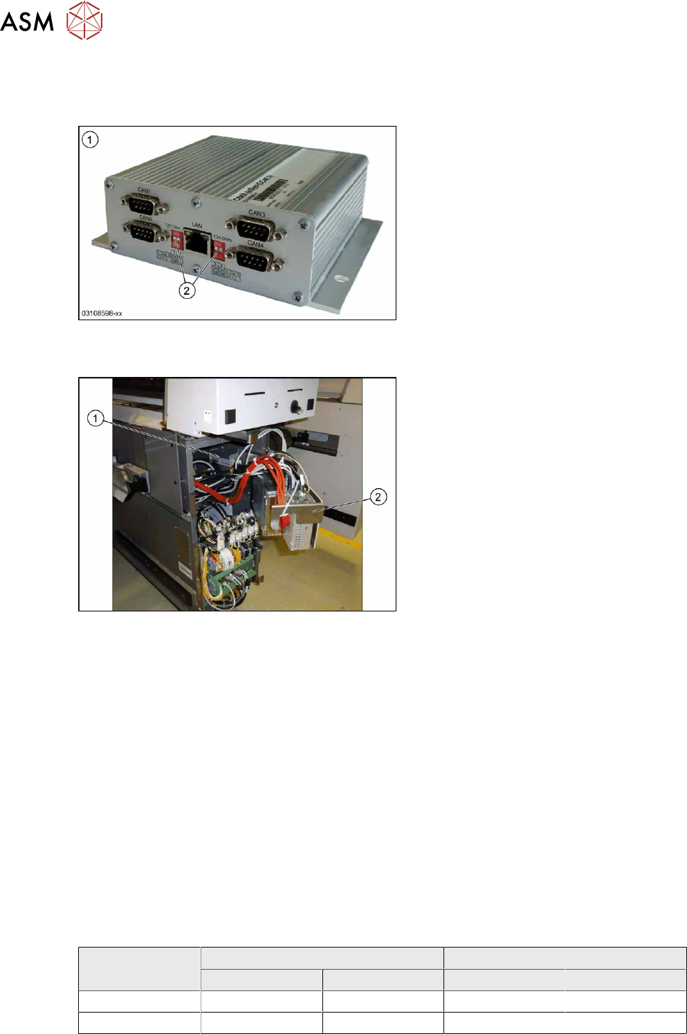
Fig.88: CAN interface CINX
1. CAN interface CINX [03108598-xx]
2. DIP switches
Overview
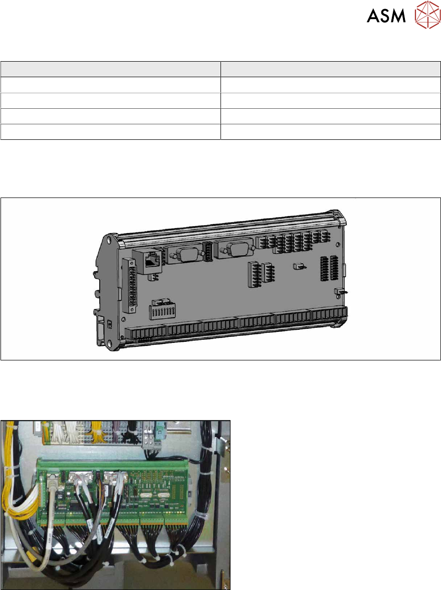
Fig.89: CAN interface in the machine
The CAN interface(1) is located between
location 1 and 2, behind the BoxPC(2)
.
The CAN interface is fixed with Velcro to the
machine base.
The CAN interface also features four con-
nections for diagnostics.
Removal
► Switch off the machine, disconnect it from the power supply and secure it to prevent
unauthorized reactivation.
1.2 "Preparatory work..." [}16]
► Lift off the keyboard (if present).
► Dismantle the lower cover between locations 1 and 2.
► Lift the BoxPC slightly and swing it forwards.
► Unplug all electrical connections to the CAN interface. Mark their positions, to make clear as-
signment easier later on.
► Take the CAN interface out of the machine.
Installation
Follow the removal instructions in reverse order for installation. Also observe the following note:
► Set the DIP switches. (see below).
DIP switch
Machine type DIP switch left DIP switch right
1 2 1 2
X-Series S ON ON ON ON
SX1/SX2 OFF OFF OFF OFF
4 Electrics and control system
4.9 Replacing the I/O control unit
Service Manual SIPLACE X-Series S (from Hxxxx) 01/2021 79
Connector
Connector Description
CAN 1 Gantry 1
CAN 2 Gantry 2
CAN 3 Gantry 3
CAN 4 Gantry 4
4.9 Replacing the I/O control unit
Parts, equipment and tools
Fig.90: I/O control unit II [03116049-xx]
●
I/O control unit II [03116049-xx]
Overview
Fig.91: I/O control unit
The I/O control unit is located between loca-
tion 1 and 2, behind the bottom cover.
Removal
► Take a note of the component counter reading at the software user interface.
► Switch off the machine, disconnect it from the power supply and secure it to prevent
unauthorized reactivation.
1.2 "Preparatory work..." [}16]
► Unplug all press-fit connections. You might like to mark their positions to make clear assign-
ment easier later on.
► Pull the I/O control unit out of its mount.
4 Electrics and control system
4.9 Replacing the I/O control unit
80 Service Manual SIPLACE X-Series S (from Hxxxx) 01/2021
Installation
Follow the removal instructions in reverse order for installation. Also observe the following instruc-
tions:
► Make sure that the DIP switches are configured correctly (see below).
► Check if the component counter of the software still matches the value you have written down.
If this is not the case, contact your SIPLACE service team.
Board description
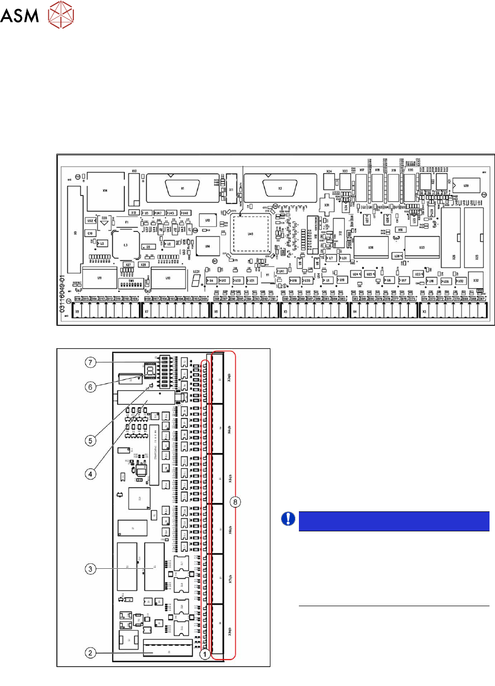
Fig.92: Overview I/O control unit II [03116049‑01]
Fig.93: Overview of I/O control unit [03052315-xx]
1. Status LEDs
2. X9qb: Power supply
3. X1qb: CAN bus 1
4. X10qb: Connection of other I/O modules
possible
5. Red LED
This signals a RESET.
6. H1: 7 segment display
(flashing = O.K.)
7. DIP switch S1
8. Outputs X3qb to X8qb
NOTICE!
Downwards compatibility
The I/O control unit II [03116049-xx] is
downwards compatible with I/O control
unit [03052315-xx].
All connections and designations are
identical.
.