00198829-01_SM_X-Series-S_Hxxxx_EN.pdf - 第81页
4 Electrics and control system 4.9 Replacing the I/O control unit Service Manual SIPLACE X-Series S (from Hxxxx) 01/2021 81 Fig.94: Overview 03052315-02 Settings on the DIP switch block S1 [03052315‑02] [03116049‑01] Sw…
4 Electrics and control system
4.9 Replacing the I/O control unit
80 Service Manual SIPLACE X-Series S (from Hxxxx) 01/2021
Installation
Follow the removal instructions in reverse order for installation. Also observe the following instruc-
tions:
► Make sure that the DIP switches are configured correctly (see below).
► Check if the component counter of the software still matches the value you have written down.
If this is not the case, contact your SIPLACE service team.
Board description
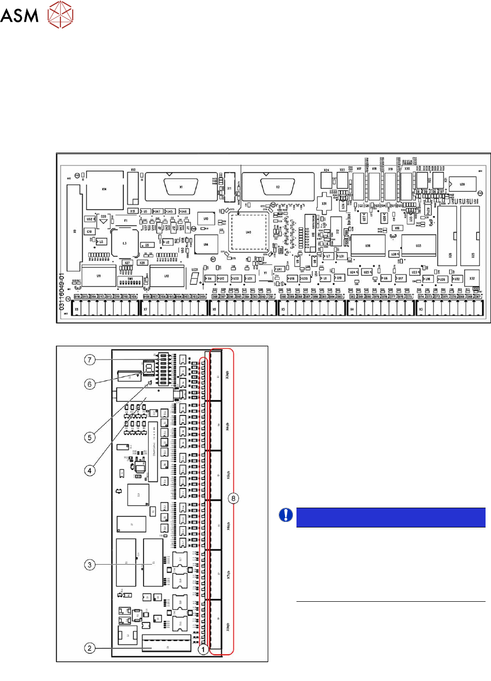
Fig.92: Overview I/O control unit II [03116049‑01]
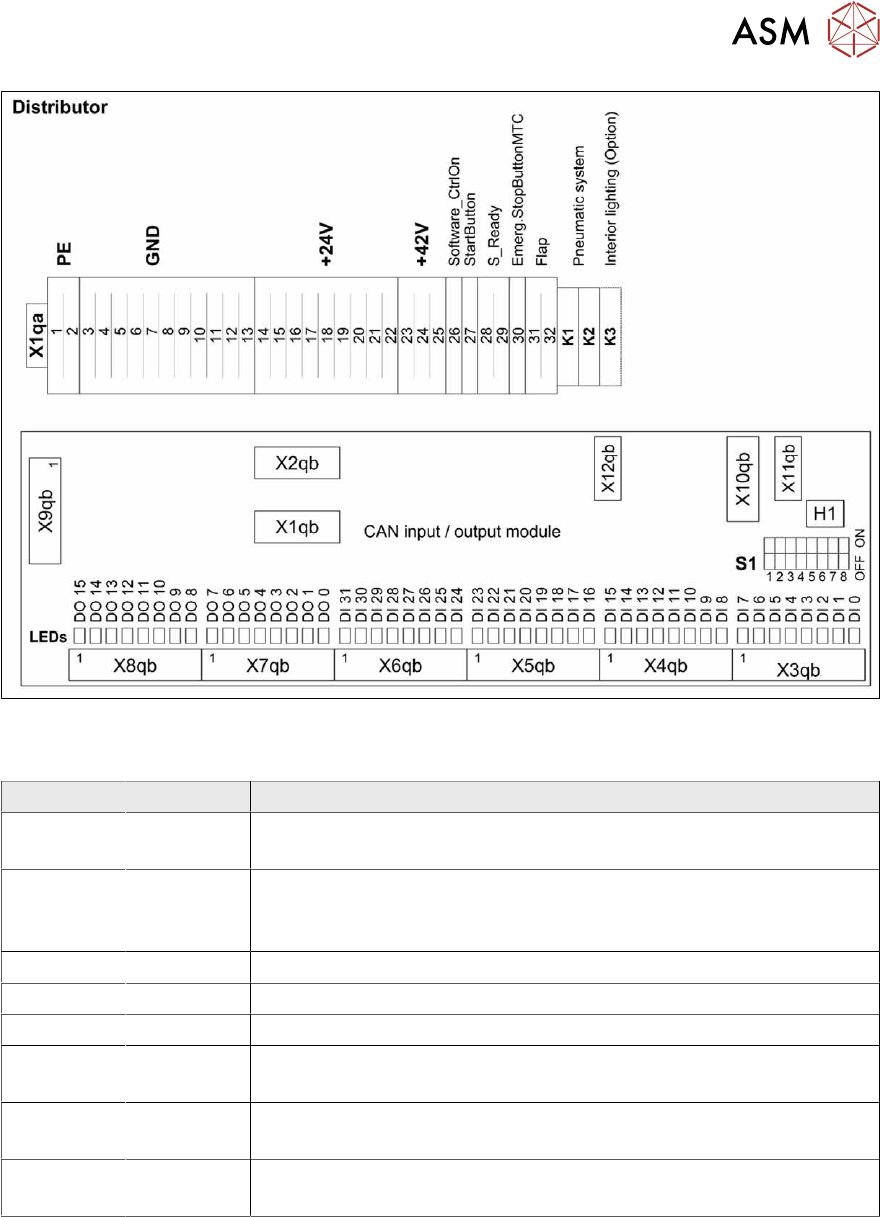
Fig.93: Overview of I/O control unit [03052315-xx]
1. Status LEDs
2. X9qb: Power supply
3. X1qb: CAN bus 1
4. X10qb: Connection of other I/O modules
possible
5. Red LED
This signals a RESET.
6. H1: 7 segment display
(flashing = O.K.)
7. DIP switch S1
8. Outputs X3qb to X8qb
NOTICE!
Downwards compatibility
The I/O control unit II [03116049-xx] is
downwards compatible with I/O control
unit [03052315-xx].
All connections and designations are
identical.
.
4 Electrics and control system
4.9 Replacing the I/O control unit
Service Manual SIPLACE X-Series S (from Hxxxx) 01/2021 81
Fig.94: Overview 03052315-02
Settings on the DIP switch block S1 [03052315‑02] [03116049‑01]
Switch Status Description
S1.1 ON/OFF ON: SX4/DX4, X-Series S
OFF: SX1/SX2, DX1/DX2
S1.2 ON/OFF Ballast resistance
ON: SX1/SX2 from machine no.: Nxxxx
OFF: SX4/DX4; X-Series S, SX1/SX2 up to machine no.: Mxxxx
S1.3 OFF Reserve
S1.4 OFF Reserve
S1.5 OFF Reserve
S1.6 OFF ON: serial bootstrap mode, make sure that S1.7 must be OFF
OFF: Standard mode
S1.7 OFF ON: CAN bootstrap mode, make sure that S1.6 must be OFF
OFF: Standard mode
S1.8 OFF ON: module in the RESET status
OFF: Standard mode
4 Electrics and control system
4.9 Replacing the I/O control unit
82 Service Manual SIPLACE X-Series S (from Hxxxx) 01/2021
Fig.95: 03052315-02
7-segment display H1 [03052315-02]
Display Status Description
Dot Flashing Circuit board OK
0 ON Firmware OK
1 ON CAN telegram cannot be transmitted
2 ON FW error: overflow in the CAN bus receiver buffer
3 ON CAN bus controller in the status ERROR PASSIVE
4 ON CAN bus controller in the status BUS OFF
5 ON Processor board received a message instead of a command
6 ON PowerFail signal active
F ON Other error
Any ON Hardware problem
A ON When initializing: BIOS mode changes to application mode
b ON When booting: head processor remains in BIOS mode